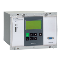
VAMP 260 Power monitoring unit
Operation and configuration
VAMP Ltd
18
Vamp 24h support phone : +358 (0)20 753 3264
VM260.EN004
4. Operating measures
General
Carefully study the operating instructions in chapters 1
through 3 of this manual before taking any operating measures
or changing any unit settings or functions.
The unit can be controlled from the unit front panel, from a PC
running the VAMPSET software, from a PC running suitable
terminal software, or from a remote control system.
4.1. Measured data
The measured values can be read from the main menus
POWER, ENERGY, PHASE CURRENTS and LINE
VOLTAGES and certain submenus below them.
4.2. Operation indicators
LED indicator Explanation Measure/ Remarks
Power LED lit
The auxiliary power has
been switched on
Normal operation state
Error LED lit
An internal unit fault has
been detected
The unit attempts to
reboot. If the error LED
remains lit, call for
maintenance.
Com LED lit or
flashing
The serial bus is in use
and transferring
information
Normal operation state
Alarm LED lit
Application related status
indicators.
Trip LED lit
Application related status
indicators.
A-C LED lit
Application related status
indicators.
Resetting latched indicators and output relays
All indicators and output relays can be given a latching
function in the configuration.
There are two ways to reset latched indicators and relays:
1. Move to the initial display, from the alarm list, by pushing
the CANCEL key for approx. 3 s. Then reset the latched
indicators and output relays by pushing the ENTER key.