VAMP Ltd Power monitoring unit
Technical description
VAMP 260
VM260.EN004 Vamp 24h support phone : +358 (0)20 753 3264
29
4. Connections
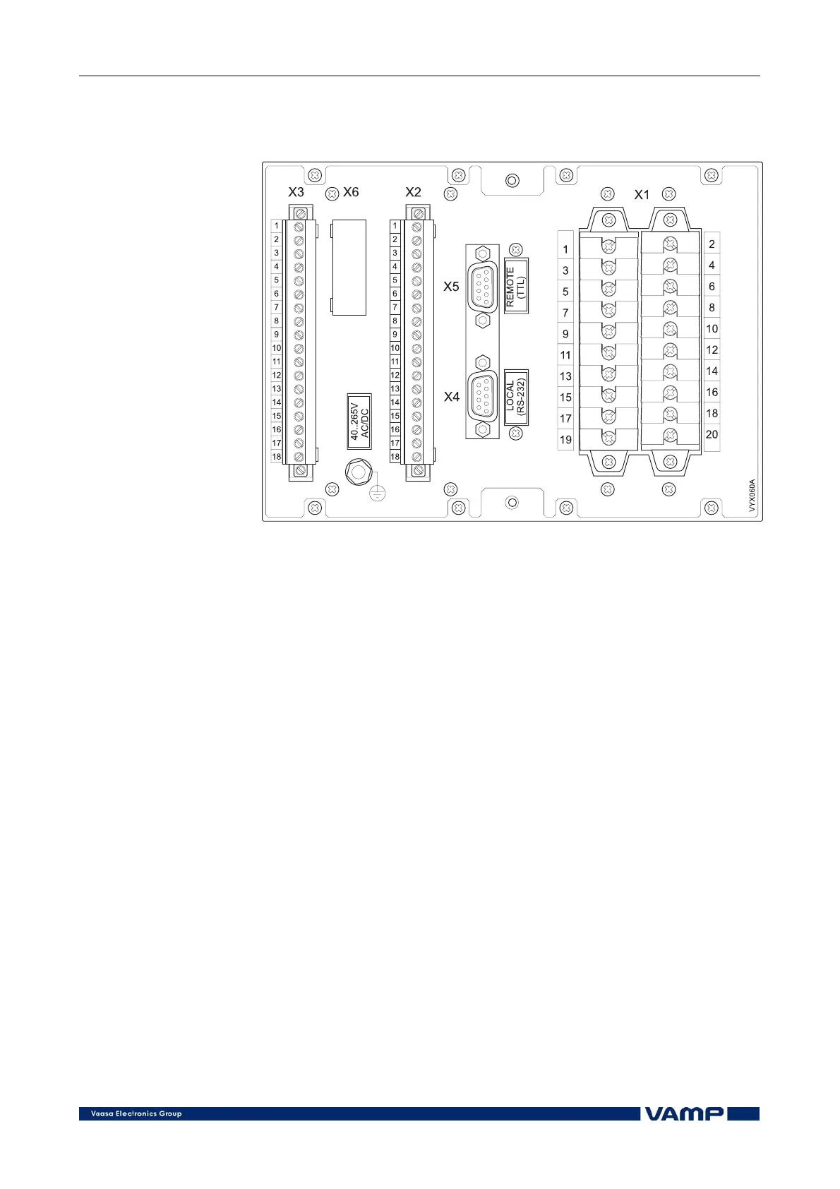
Figure 4-1. Connections on the rear panel of the unit.
The VAMP 260 measuring unit is connected to the protected
object through the following measuring and control
connections, Figure 4-1:
• Phase currents I
L1
, I
L2
and I
L3
(terminals X1: 1-6)
• Line voltages U
a
, U
b
and U
c
(terminals X1: 11-16)
4.1. Digital inputs
Further the measuring unit can collect status information and
alarm signals via six digital inputs (terminals X3: 2-7).
The digital inputs can i.e. be used to:
• Block protection stages under certain conditions.
• Get time stamped event code from any auxiliary
contact.
• Control the output relays.
The digital inputs use the internal 48 V dc auxiliary voltage of
the unit (terminal X3: 1). Potential-free contacts must be
available in the protected object for transfer of status
information to the unit.