VAMP Ltd Power monitoring unit
Technical description
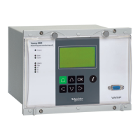
VAMP 260
VM260.EN004 Vamp 24h support phone : +358 (0)20 753 3264
19
2.5. Logic functions
The device supports customer-defined logics. The logics are
designed by using the VAMPSET setting tool and downloaded
to the terminal. For detailed information, please refer to the
VAMPSET manual (VMV.EN0xx).
2.6. Programmable alarm functions
Power monitoring unit has eight identical programmable alarm
stages (ALARM STAGE 1-8). All alarm stages can be enabled
or disabled one by one from the menu (Alrm/ALARM 1...ENA)
to fit the intended application. All the enabled alarm stages
have the following programmable parameters:
• Link_: link to a measured or calculated value, see table
below.
• Cmp_: mode (< or >)
• Set_: alarm limit of stage_ (setting range depends on the
signal)
• t: delay 0.5 - 300.0 s, step 0.1 s
• Hyst_: hysteresis 1.0 - 10,0%, step 0.1%
• NoCmp_: no compare limit (visible only for active < mode)
Alarm stage link signals
Alarm stages link signals Interval
P, Q, S, f, P.F, cosϕ, tanϕ
200 ms mean
IL1 – IL3, IL, IL max of IL1 – IL3
Io, I1, I2, I2/I1
U12, U23, U31, U
U max of U12 – U23, U min of U12 – U23
UL1 – UL3, Uphase, Uphmin, Uphmax of UL1 – UL3
Uo, U1, U2, U2/U1
THDIL1, THDIL2, THDIL3, THDUa,THDUb, THDUc 500 ms
User’s averages 1 – 8 1.00 – 900 s
DI1 – DI6 100 ms
SW1, SW2
The outputs of the alarm stages can control any combination of
output relays and indicator LEDs, see Figure 2.6-1 and Figure
2.6-2