Technical description 2 Protection functions 2.7 Current unbalance stage I2>
46
VM50.EN004 VAMP 24h support phone +358 (0)20 753 3264
55
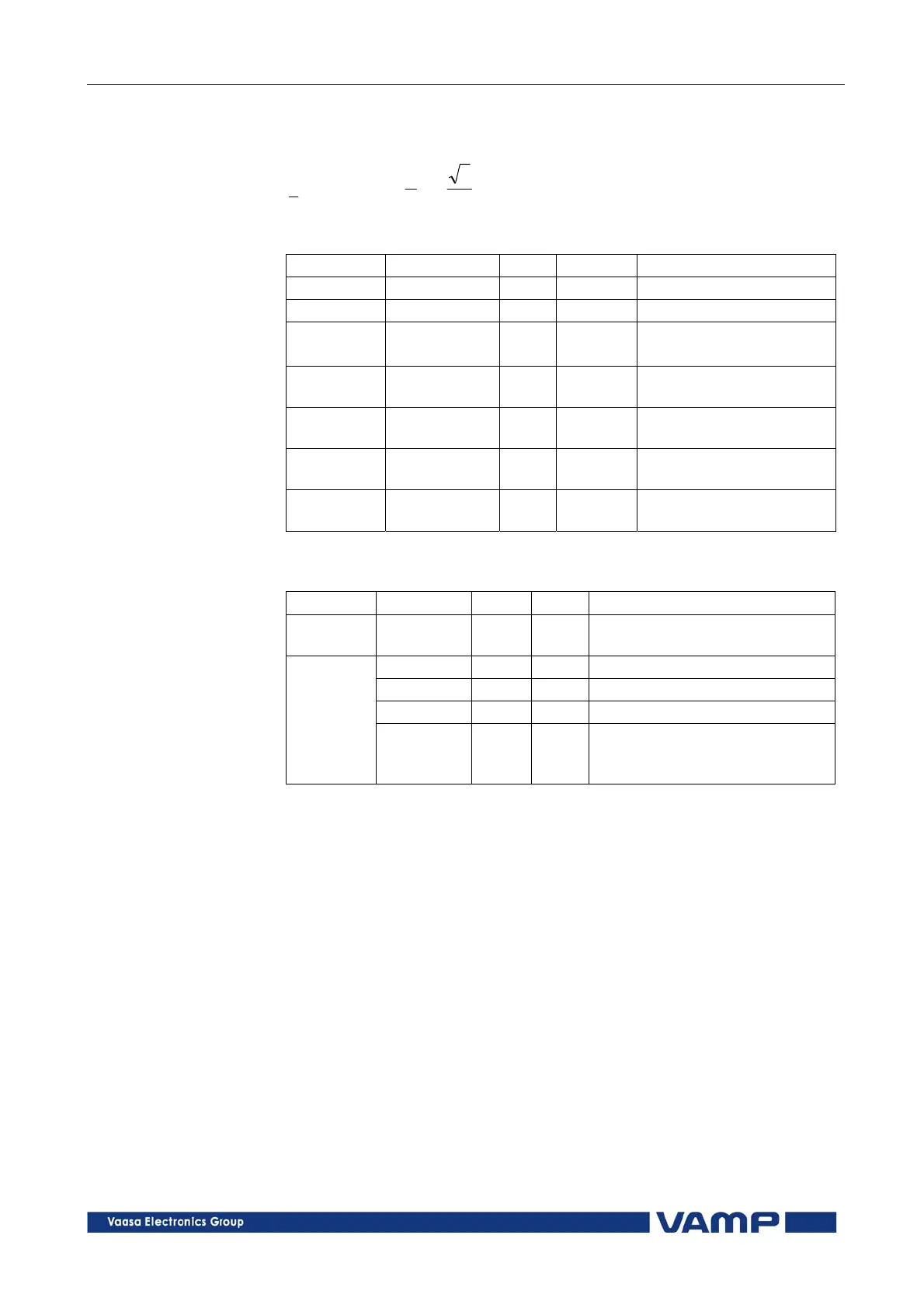
I1 = I
L1
+ aI
L2
+ a
2
I
L3
I2 = I
L1
+ a
2
I
L2
+ aI
L3
2
3
2
1
1201 ja
, a phasor rotating constant
Setting parameters of unbalanced load function I
2
/I
1
> (46R):
Parameter Value Unit Default Description
I2/I1> 2 … 70 % 20 Setting value, I2/I1
t> 1.0 … 600.0 s 10.0 Definite operating time
Type DT
INV
- DT
The selection of time
characteristics
S_On
Enabled;
Disabled
- Enabled Start on event
S_Off
Enabled;
Disabled
- Enabled Start off event
T_On
Enabled;
Disabled
- Enabled Trip on event
T_Off
Enabled;
Disabled
- Enabled Trip off event
Measured and recorded values of unbalanced load function
I
2
/I
1
> (46R):
Parameter Value Unit Description
Measured
value
I2/I1 %
Relative negative sequence
component
SCntr Cumulative start counter
TCntr Cumulative start counter
Flt % Maximum I
2
/I
1
fault component
Recorded
values
EDly %
Elapsed time as compared to
the set operating time, 100% =
tripping
2.7. Current unbalance stage I
2
> (46)
Current unbalance in a motor causes double frequency currents
in the rotor. This warms up the surface of the rotor and the
available thermal capacity of the rotor is much less than the
thermal capacity of the whole motor. Thus an rms current
based overload protection (see chapter 2.16) is not capable to
protect a
motor against current unbalance.
The current unbalance protection is based on the negative
sequence of the base frequency phase currents. Both definite
time and inverse time characteristics are available.