Technical description 2 Protection functions 2.13 Earth fault protection I0>
50N/51N
VM50.EN004 VAMP 24h support phone +358 (0)20 753 3264
69
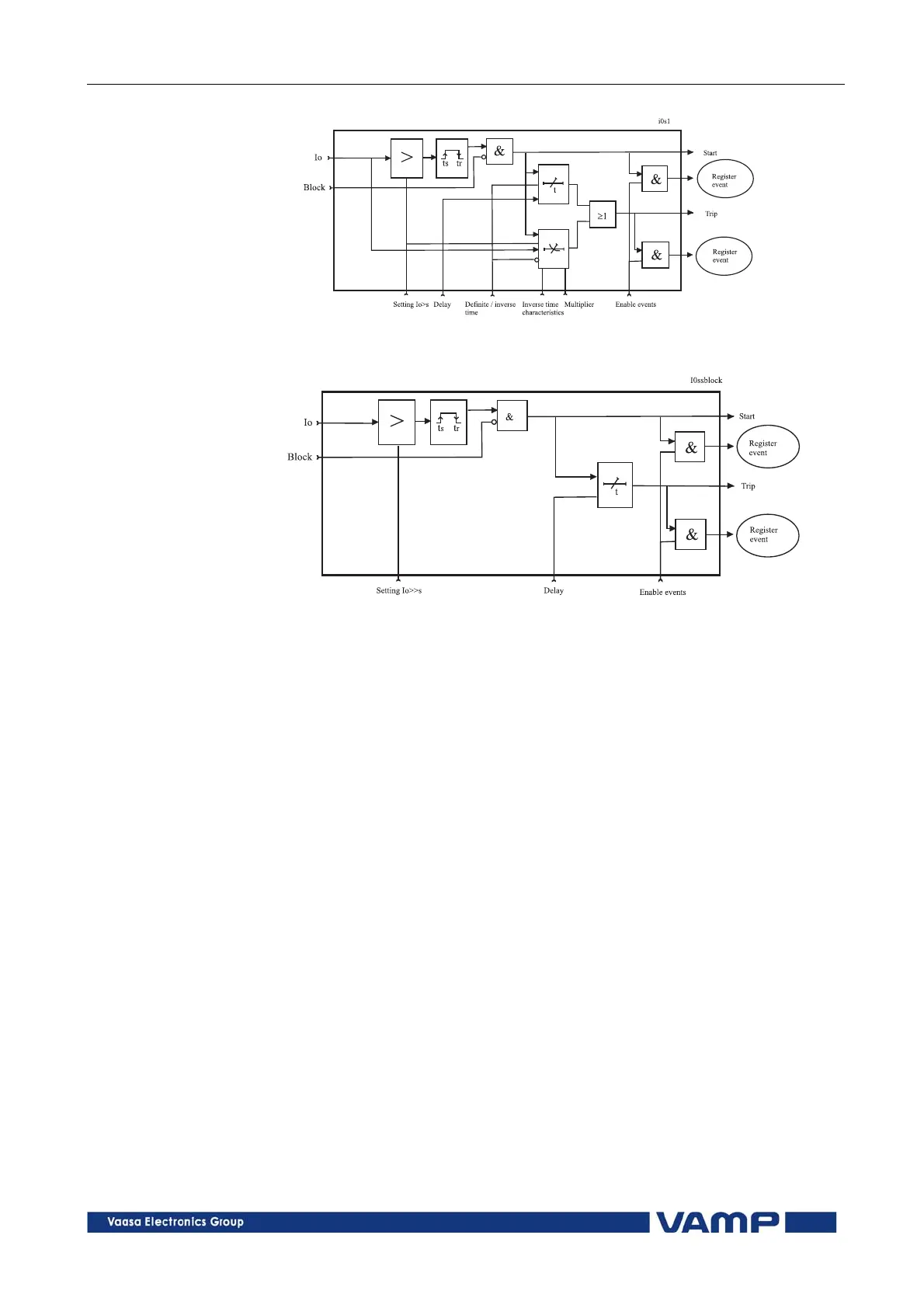
Figure 2-1 Block diagram of the earth fault stage I
0
>
Figure 2-2 Block diagram of the earth fault stages I
0
>>, I
0
>>> and I
0
>>>>
Figure 2-1 shows a functional block diagram of the I
0
> earth
overcurrent stage with definite time and inverse time operation
time. Figure 2-2 shows a functional block diagram of the I
0
>>,
I
0
>>> and I
0
>>>> earth fault stages with definite time
operation delay.
Input signal selection
Each stage can be connected to supervise any of the following
inputs and signals:
Input I
01
for all networks other than rigidly earthed.
Calculated signal I
0Calc
for rigidly and low impedance
earthed networks. I
0Calc
= I
L1
+ I
L2
+ I
L3
.
Additionally the stage I
0
> has one more input signal
alternative to measure current peaks to detect a restriking
intermittent earth fault:
I
01Peak
to measure the peak value of input I
01
.
Intermittent earth fault detection
Short earth faults make the protection to start (pick up), but
will not cause trip. W
hen starting happens often enough, such
intermittent faults can be cleared using the intermittent time
setting.