Technical description 2 Protection functions 2.15 Zero sequence volta
e
protection U0>
59N
VM50.EN004 VAMP 24h support phone +358 (0)20 753 3264
79
Whenever the measured value exceeds the user's pick-up
setting of a particular stage, this stage picks up and a start
signal is issued. If the fault situation remains on longer than
the user's operation time delay setting, a trip signal is issued.
Measuring the zero sequence voltage
The zero sequence voltage is either measured with three
voltage transformers (e.g. broken delta connection), one voltage
transformer between the motor's neutral point and earth (see
chapter 4.7):
U
0
: The zero sequence voltage is measured with voltage
transformer(s) for example using a broken delta connection.
The setting values are relative to the VT
0
secondary voltage
defined in configuration.
NOTE! The U
0
signal must be connected according the connection diagram
(Figure 8.10.2-1) in order to get a correct polarization. Please note that
actually the
negative U
0
, U
0
, is to be connected to the device.
Two independent stages
There are two separately adjustable stages: U
0
> and U
0
>>.
Both stages can be configured for definite time (DT) operation
characteristic.
The zero sequence voltage function comprises two separately
adjust-table zero sequence voltage stages (stage U
0
> and U
0
>>).
Setting groups
There are two settings groups available for both stages.
Switching between setting groups can be controlled by digital
inputs, virtual inputs (communication, logic) and manually.
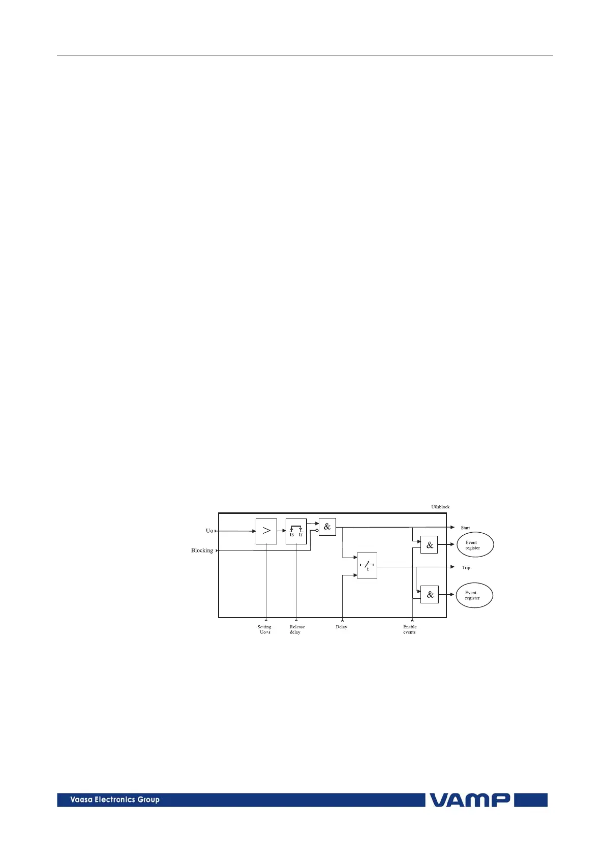
Figure 2.15-1. Block diagram of the zero sequence voltage stages U
0
> and
U
0
>>