Technical description 2 Protection functions 2.14 Intermittent transient earth faul
protection I0T>
67NT
VM50.EN004 VAMP 24h support phone +358 (0)20 753 3264
77
Setting groups
There are two settings groups available. Switching between
setting groups can be controlled by digital inputs, virtual
inputs (mimic display, communication, logic) and manually.
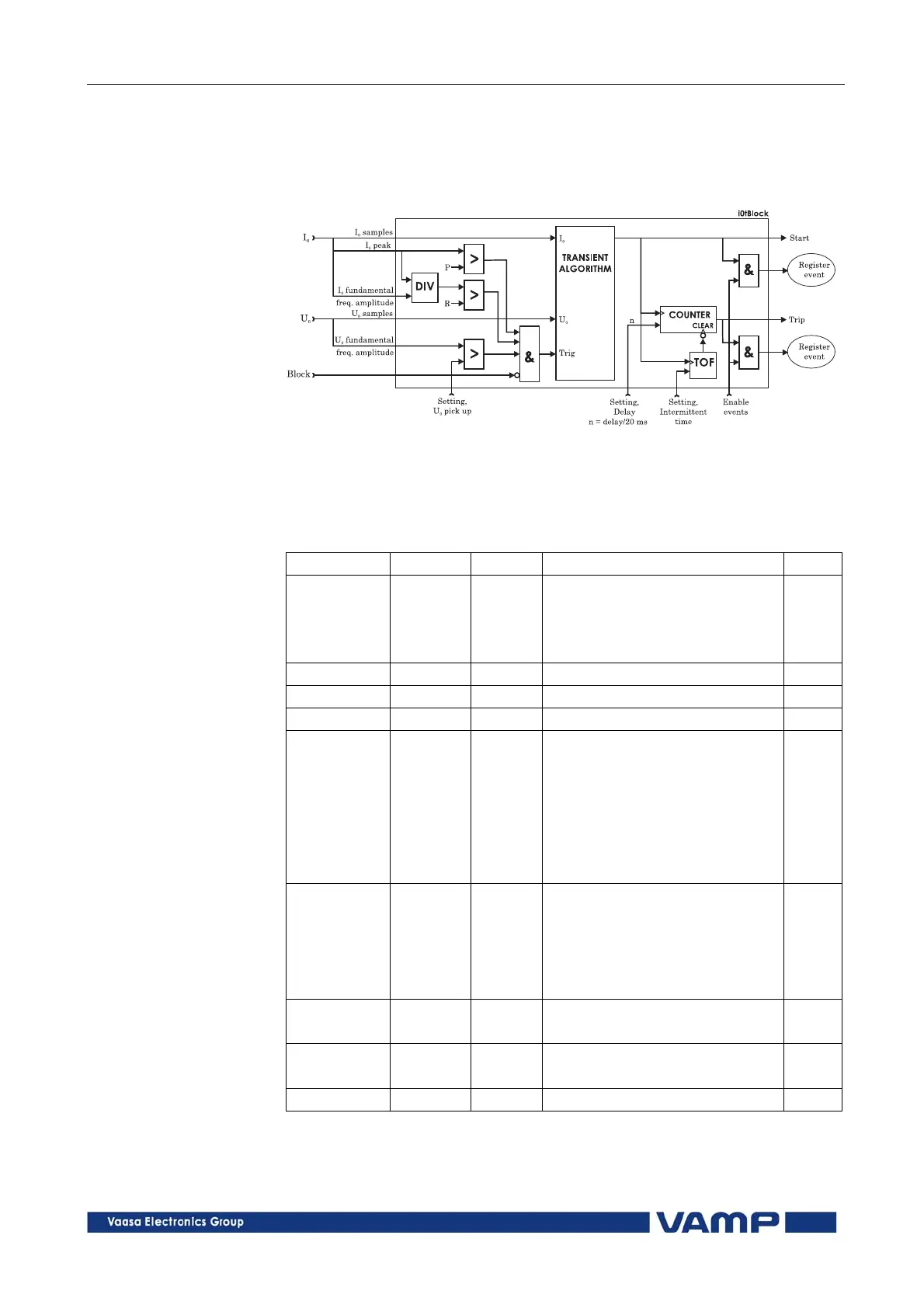
Figure 2.14-3. Block diagram of the directional intermittent transient earth
fault stage I
0T
>.
Parameters of the directional intermittent transient earth fault
stage I
0T
> (67NT)
Parameter Value Unit Description Note
Status -
Blocked
Start
Trip
Current status of the stage
F
F
SCntr Cumulative start counter Clr
TCntr Cumulative trip counter Clr
SetGrp 1 or 2 Active setting group Set
SGrpDI
-
DIx
VIx
LEDx
VOx
Digital signal to select the
active setting group
None
Digital input
Virtual input
LED indicator signal
Virtual output
Set
Force Off
On
Force flag for status forcing for
test purposes. This is a
common flag for all stages and
output relays, too.
Automatically reset after a five
minute timeout.
Set
Io1
Io2
pu
The detected I
0
value according
the parameter "Input" below.
Uo % The measured U
0
value.
U
0N
= 100 %
Uo> % U
0
pick up level. U
0N
= 100 % Set