2.21 Programmable stages (99) 2 Protection functions Technical description
92
VAMP 24h support phone +358 (0)20 753 3264 VM50.EN004
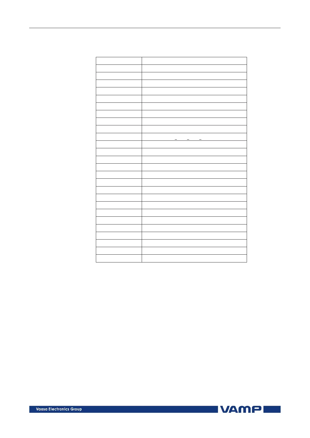
Table 2.21-1Available signals to be supervised by the
programmable stages
IL1, IL2, IL3 Phase currents
Io Residual current input I
0
U12, U23, U31 Line-to-line voltages
UL1, UL2, UL3 Phase-to-ground voltages
Uo Zero-sequence voltage
f Frequency
P Active power
Q Reactive power
S Apparent power
Cos Fii
Cosine
IoCalc Phasor sum I
L1
+ I
L2
+ I
L3
I1 Positive sequence current
I2 Negative sequence current
I2/I1 Relative negative sequence current
I2/In Negative sequence current in pu
IL Average (I
L1
+ I
L2
+ I
L3)
/3
TanFii
Tangent [=tan(arccos)]
Prms Active power rms value
Qrms Reactive power rms value
Srms Apparent powre rms value
THDIL1 Total harmonic distortion of I
L1
THDIL2 Total harmonic distortion of I
L2
THDIL3 Total harmonic distortion of I
L3
THDUa Total harmonic distortion of input U
a
IL1rms IL1 RMS for average sampling
IL2rms IL2 RMS for average sampling
IL3rms IL3 RMS for average sampling
Eight independent stages
The device has eight independent programmable stages. Each
programmable stage can be enabled or disabled to fit the
intended application.
Setting groups
There are two settin
gs groups available. Switching between
setting groups can be controlled by digital inputs, virtual
inputs (communication, logic) and manually.
There are two identical stages available with independent
setting parameters.