Technical description 2 Protection functions 2.16 Thermal overload protection T>
49
VM50.EN004 VAMP 24h support phone +358 (0)20 753 3264
83
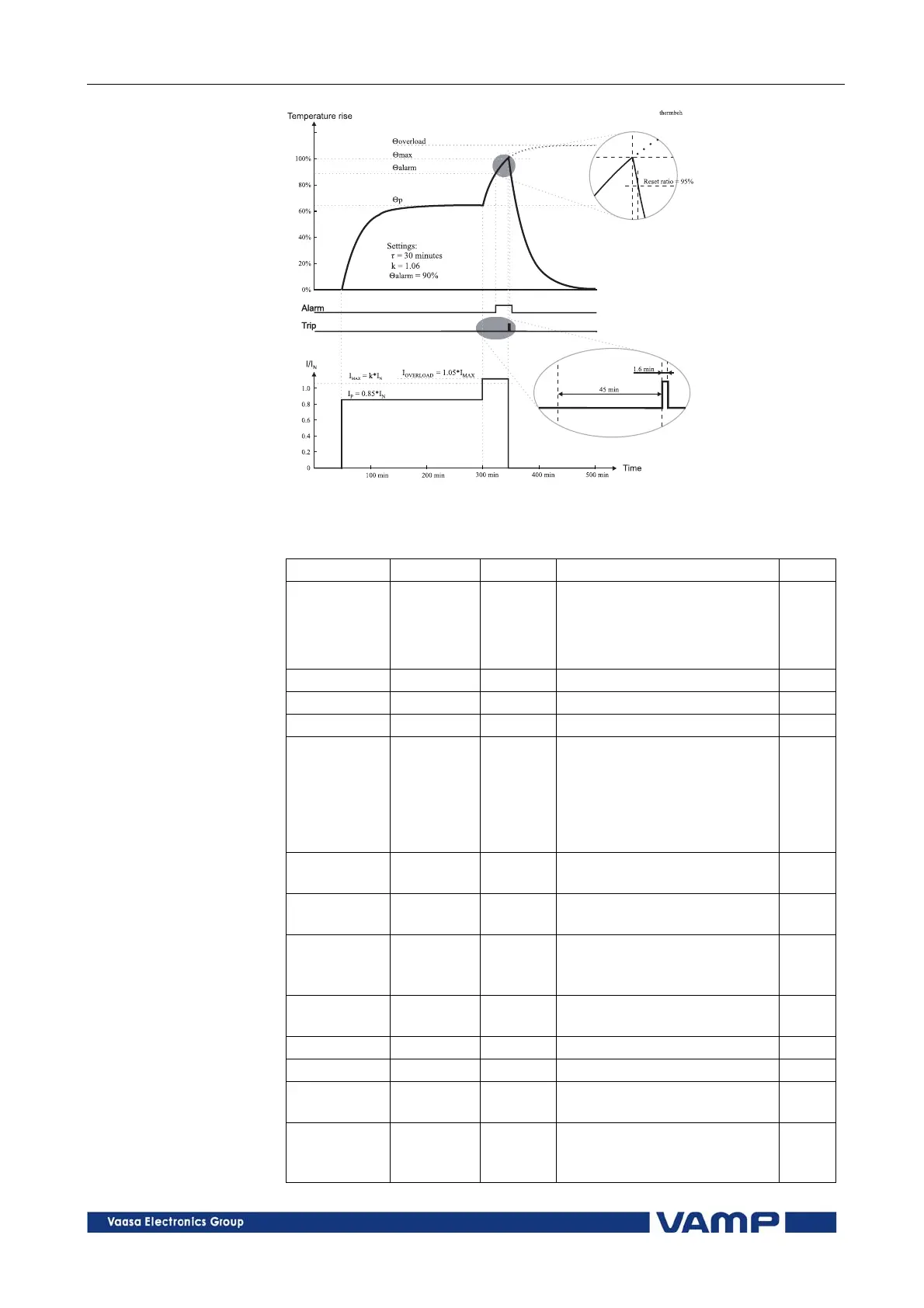
Figure 2.16-2. Example of the thermal model behaviour.
Parameters of the thermal overload stage T> (49)
Parameter Value Unit Description Note
Status -
Blocked
Start
Trip
Current status of the stage
F
F
Time hh:mm:ss Estimated time to trip
SCntr Cumulative start counter C
TCntr Cumulative trip counter C
Force Off
On
Force flag for status forcing
for test purposes. This is a
common flag for all stages
and output relays, too.
Automatically reset by a 5-
minute timeout.
Set
T %
Calculated temperature
rise. Trip limit is 100 %.
F
MaxRMS Arms
Measured current. Highest
of the three phases.
Imax A
kxIn. Current corresponding
to the 100 % temperature
rise.
k> xImode
Allowed overload (service
factor)
Set
Alarm % Alarm level Set
tau min Thermal time constant Set
ctau xtau
Coefficient for cooling time
constant. Default = 1.0
Set
kTamb xImode
Ambient temperature
corrected max. allowed
continuous current