SECTION 3: INSTALLATION
090189-OP_r0 (JUNE-2022) 3 - 3
VANAIR MANUFACTURING, INC.
(844) VAN-SERV • www.vanair.com
Cap•Start Hydraulic-Driven
12V/24V • Battery Starter • Charger
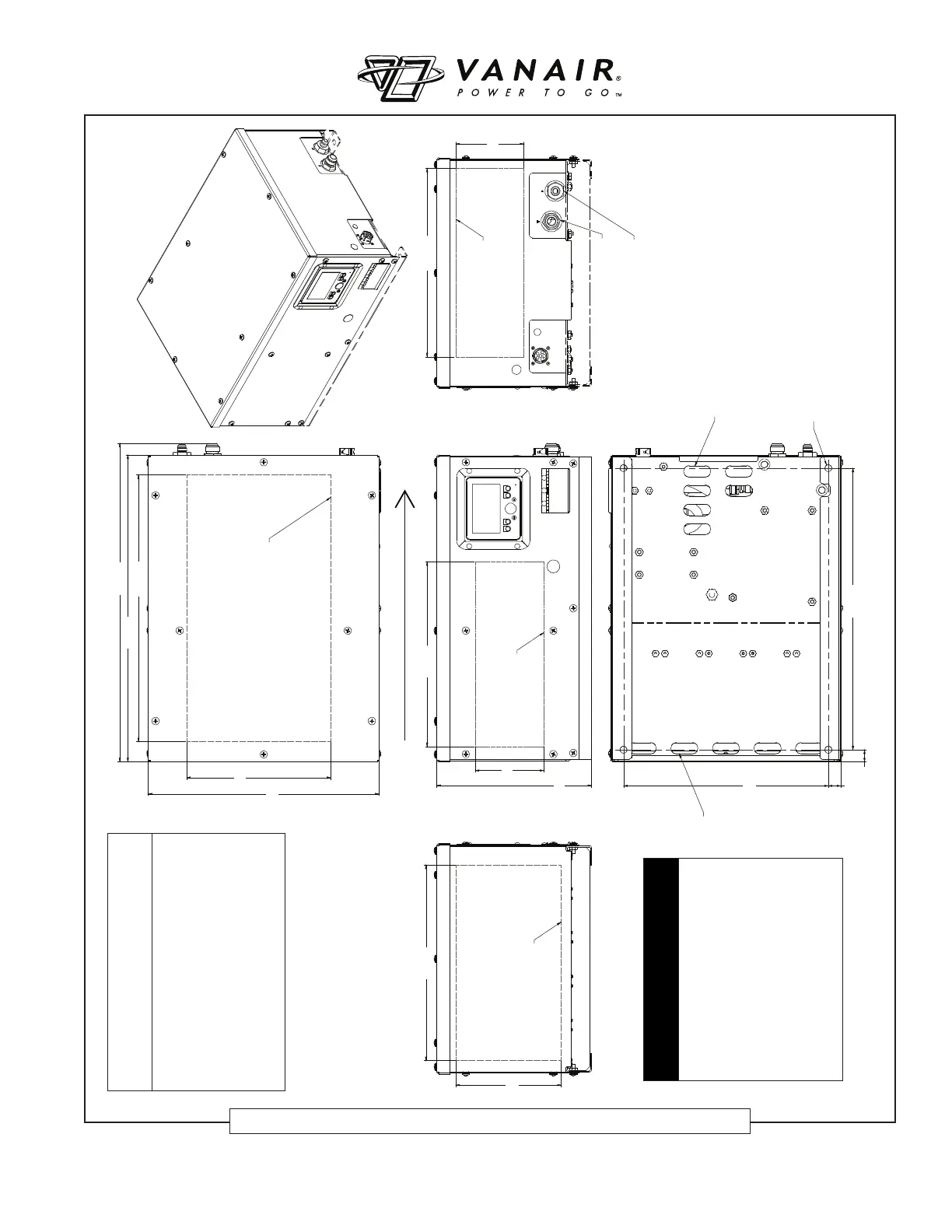
20.83
24.00
11.25
18.00
5.34
12.11
Ø0.55
(4X)
16.00
14.43 14.73
5.30
8.23
15.31
DECAL AREA
AIR FLOW
DECAL AREA
DECAL AREA
DECAL AREA
AIR
FLOW
IN
AIR FLOW OUT
24.92
HYDRAULIC RETURN
#12 MJIC 37°
HYDRAULIC SUPPLY
#8 MJIC 37°
0.98
0.95
22.00
Figure 3-2: Identifi cation and Dimension Diagram
DISCLAIMER
If machine package is to be
mounted within a confi ned
space such as beneath a can-
opy, the area must be deter-
mined to allow for adequate air
fl ow to take place for cooling
purposes. Consult factory for
assistance in ensuring ade-
quate air fl ow before mounting
the machine.
NOTE
The dimensions listed in this
diagram are the minimum required
clearance distances needed for
properly cooling the machine.
Additional clearance room may be
desired for easier access for control
and/or maintenance functions.
050211ID_r0