SECTION 3: INSTALLATION
3 - 4
090189-OP_r0 (JUNE-2022)
VANAIR MANUFACTURING, INC.
(844) VAN-SERV • www.vanair.com
Cap•Start Hydraulic-Driven
12V/24V • Battery Starter • Charger
IMPORTANT
Contaminated hydraulic fl uid allowed to enter
the pump will cause malfunction of the pump
controls. Hydraulic system hoses must be
fl ushed and cleaned prior to being connected to
the unit.
Refer to Figure 3-2 for hydraulic pump system
connections.
Please take into consideration the following:
• The hydraulic fl ow and pressure requirements
of the system.
• A continuous hydraulic load is necessary when
machine is running.
• The duty cycle and ambient operating tempera-
tures.
• Other hydraulic equipment which may share
that same hydraulic supply system (Vanair
recommends a dedicated pump and hydraulic
circuit).
WARNING
Follow all applicable safety recommendations
as outlined in Section 1: Safety of this manual.
WARNING
Improperly, or non-connected lines may cause
harm, and will damage the equipment.
The hydraulic hoses must be run to the machine.
Verify that hoses are hooked up properly to en-
sure proper fl ow. Also, verify that the hoses are
laid out properly so that no chafi ng or kinking
of the hoses is possible. Refer to Section 7.12,
Hose Installation Guide, for assistance with
proper hose layout and connecting functions.
NOTE
The temperature of the hydraulic oil should not
exceed 160°F due to the rating of the Vanair-
supplied hydraulic motor.
3.4.1 HYDRAULIC SYSTEM
FILTRATION
Vanair recommends using a 10 micron oil fi lter on
the hydraulic oil return line. Flow rating of the fi lter
must be equal to, or greater than, the maximum
GPM at which the system will be operated.
IMPORTANT
Use only a fi lter that is specifi cally intended for
hydraulic systems.
3.4.2 HYDRAULIC OIL RESERVOIR
3.4.2.1 DETERMINING RESERVOIR
SIZE
In a conventional hydraulic system, minimum
tank size, in gallons, should be equal to the max-
imum GPM fl ow rate, times two (x 2).
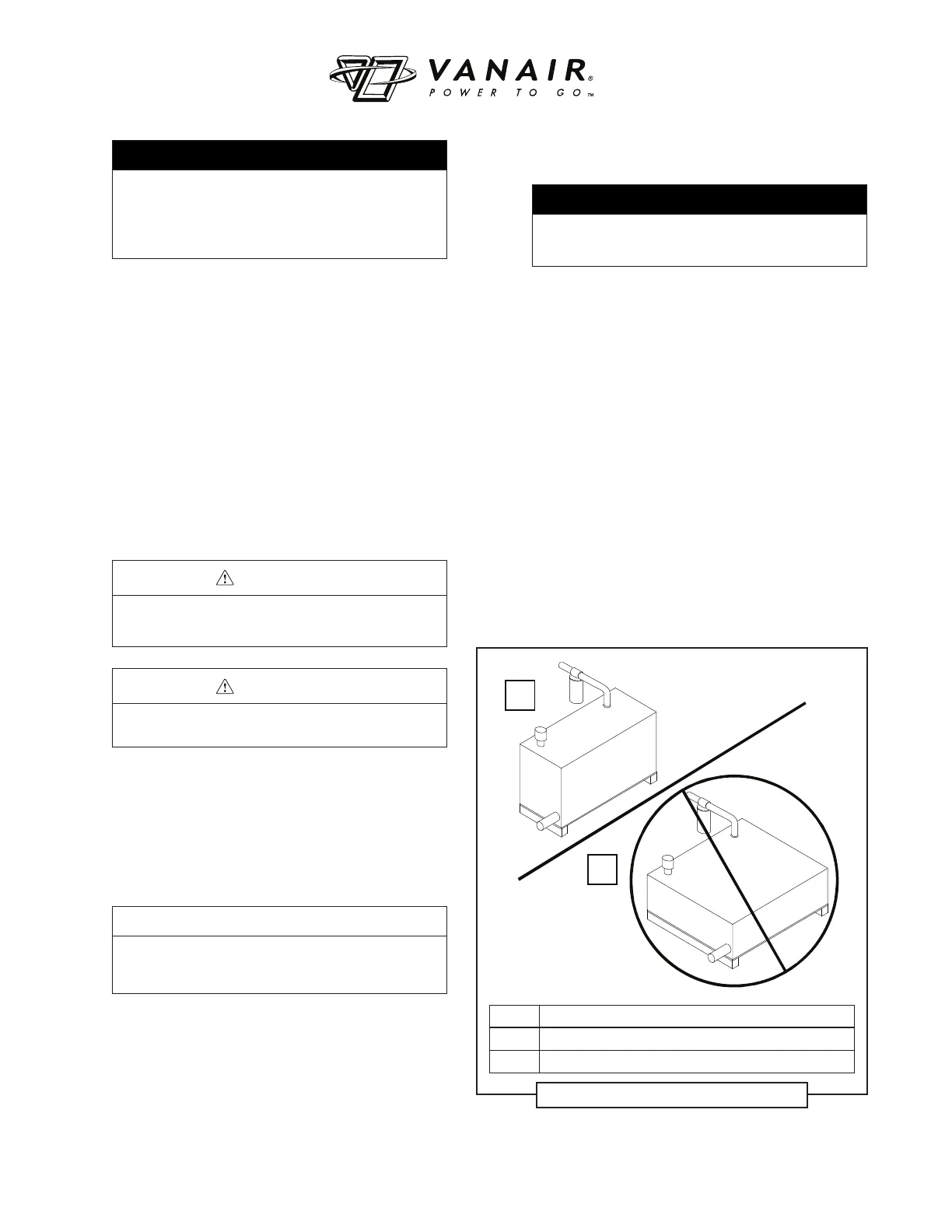
3.4.2.2 DETERMINING
RESERVOIR SHAPE
The reservoir structure should be tall and narrow
rather than shallow and broad (Figure 3-3). A tall,
narrow tank is recommended because:
1. The oil level is well above suction line open-
ing, avoiding the possibility of drawing air into
the pump due to a vortex or “whirlpool” eff ect
within the tank during operation fl ow.
A
B
KEY DESCRIPTION
A PREFERRED SHAPE: TALL AND NARROW
B SHAPE TO AVOID: BROAD AND SHALLOW
Figure 3-3: Reservoir Design Shape