SECTION 3: INSTALLATION
3 - 2
090189-OP_r0 (JUNE-2022)
VANAIR MANUFACTURING, INC.
(844) VAN-SERV • www.vanair.com
Cap•Start Hydraulic-Driven
12V/24V • Battery Starter • Charger
3.3 DETERMINING THE MACHINE
MOUNTING LOCATION
When determining the location to mount the
Cap•Start Hydraulic unit, the following criteria
must be taken into consideration:
• The mounting surface must be level and able to
accommodate the four (4) mounting bolts and
isolators of the base frame. Refer to Figure
3-1 or Figure 3-2 for clearance room and lay-
out of mounting hole slots’ locations.
IMPORTANT
Mounting surface must be able to bear the
weight of the machine (245 lbs).
• Mount the machine with a minimum of four (4)
mounting locations.
• The location must allow for the machine dimen-
sions, and additional space requirements for
minimum cooling, maintenance and access.
Refer to Figure 3-3 to determine the additional
minimum space requirement measurements.
• The external gauges/display must be easily vis-
ible to the operator.
It is recommended, for most installations, to
mount the
machine on the driver’s side of the ve-
hicle. The unit should be situated in such a man-
ner that the fan (rear) and hydraulic cooler (front)
are not obstructed. Do not place the
machine in
any location where it can ingest exhaust fumes,
dust or debris.
NOTE
When considering external system layout hoses
refer to Section
7.12, Hose Guide for proper
routing and mounting practices.
3.4 HYDRAULIC SYSTEM
OVERVIEW
IMPORTANT
Vanair
®
highly recommends consulting a hy-
draulic supply expert for specifying the correct
hydraulic supply components for vehicle-side
integration (including oil reservoir size, hy-
draulic pressure relief, hose size, etc.) for your
application.
A
B
B
C
C
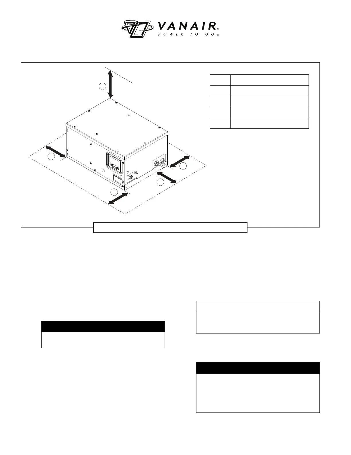
Figure 3-1: Machine Minimum Operational Clearance
KEY DESCRIPTION
A MINIMUM CLEARANCE: 8"
B MINIMUM CLEARANCE: 8"
C MINIMUM CLEARANCE: 8"
D MINIMUM CLEARANCE: 8"