~ 15 ~
COM3000 Integrator’s Installation Manual
7 THE COM400 CHASSIS
The COM400 Chassis houses, powers and connects the COM51 to QAM4 and provides ethernet connections. It
has an internal layer 2 ethernet switch. The default settings are adequate for most installations.
If the system is a QAM based RF output, skip this section, and continue to COM51 configurations.
7.1 ACCESSING THE COM400 CHASSIS
To determine the IP address of the COM400 user interface use the following formula:
192.168.10. (chassis id +1)
For most single chassis configurations this would equate to 192.168.10.2
Login is Admin, leave Password field blank.
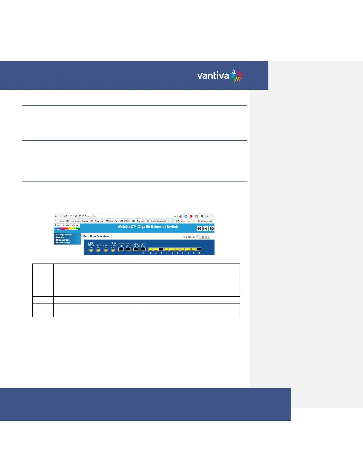
7.2 PORT STATE OVERVIEW
The first page of the interface displays the Port State overview.
Ports 1-11 are utilized in the COM400 chassis and are displayed as lit when connection to each port is made.
In the example below all ports are connected except #7, the top QAM port.
Internal unmanaged Ethernet switch to both 1
GIG ports
Note: Both 1 gigabit ports are connected to the same port on the layer 2 switch via an unmanaged Ethernet
switch. All multicast traffic requested by one port will be present on the other. For this reason, it is
recommended that the 1 gigabit ports not be used for multicast traffic.