VCC 112T, index I
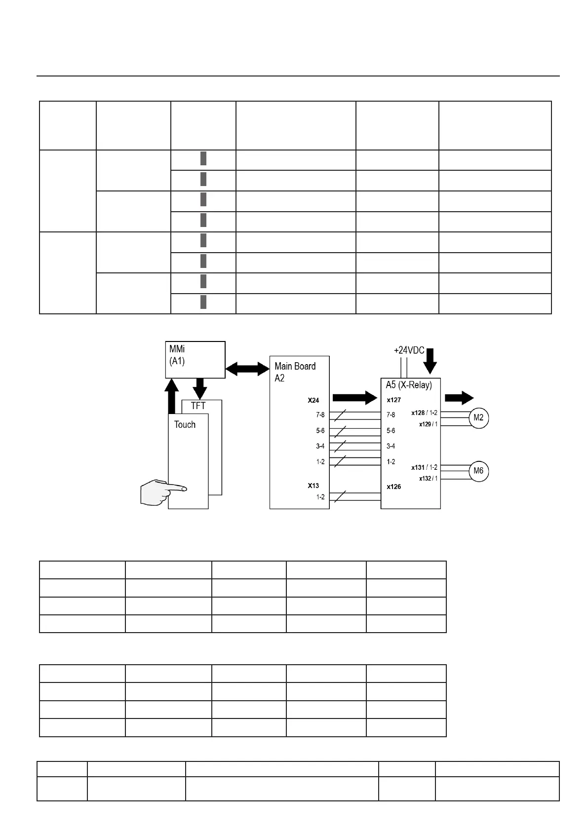
Control of movements, principle
Summary table of movement control signals
Side Element Action Board A2
Connector X24
(12VDC)
Board A2
X13
(12VAC)
Board A5
(24-28 VDC)
Left Pan
↑ X24: 1/2 X128 1(-) / 2(+)
↓ X24: 1/2 + 3/4 X128 1(+) / 2(-)
Autolift
Lid
↑ X24: 1/2 + 5/6 X128 2(+) / X129 1(-)
↓ X24: 1/2 + 3/4 + 5/6 X128 2(-) / X129 1(+)
Right Pan
↑ X24: 1/2 X13 : 1/2 X131 1(-) / 2(+)
↓ X24: 1/2 + 3/4 X13: 1/2 X131 1(+) / 2(-)
Autolift
Lid
↑ X24: 1/2 + 5/6 X13: 1/2 X131 2(+) / X132 1(-)
↓ X24: 1/2 + 3/4 + 5/6 X13: 1/2 X131 2(-) / X132 1(+)
Wiring
Summary table of limit switch states
●Fig1 Leftside
Lid Pan S10 S25 S27
Up Down
1 1 0
Up Up
1 0 1
Down Down
0 1 0
●Fig.2 Rightside
Lid Pan S12 S26 S28
Up Down
1 1 0
Up Up
1 0 1
Down Down
0 1 0
X.05
v03 • July-2016 • Hen
Motorisation Module
Line Units Serial number (starting from) Sw Revision
VCCM
VCCWE
112T E12VI1310xxxxxxx