Series 613 INSTALLATION
984360EC Edition 12.08.2022 25/
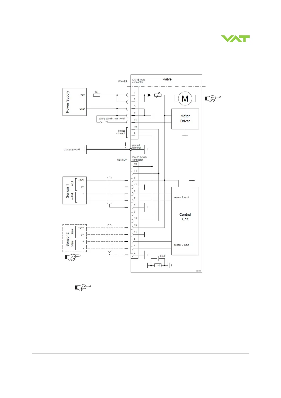
5.5.3.1 Power and 24V sensor connection
[61. . . - . . G . - . . . . / 61. . . - . . H . - . . . . versions recommended]
•
VAT fuse recommendation: (a) 3 AF
•
Use shielded sensor cable(s). Keep cable as short as possible, but locate it away
from noise sources.
•
Connector: Use only screws with 4–40 UNC thread for fastening the connectors!
Pins 4 and 11 must be
bridged for operation.
An optional switch
would allow for motor
interlock to prevent
valve from moving.
Low range sensor may be con-
nected to sensor 1 or sensor 2
input. Do configuration accordingly

 Loading...


