Installation, Operating & Maintenance Instructions
Series 650 DN 100-250 (I.D. 4“ - 10”), CC-Link
VAT Vakuumventile AG, CH-9469 Haag, Switzerland
Tel +41 81 771 61 61 Fax +41 81 771 48 30 CH@vatvalve.com www.vatvalve.com
280672EB
2010-12-15
19/94
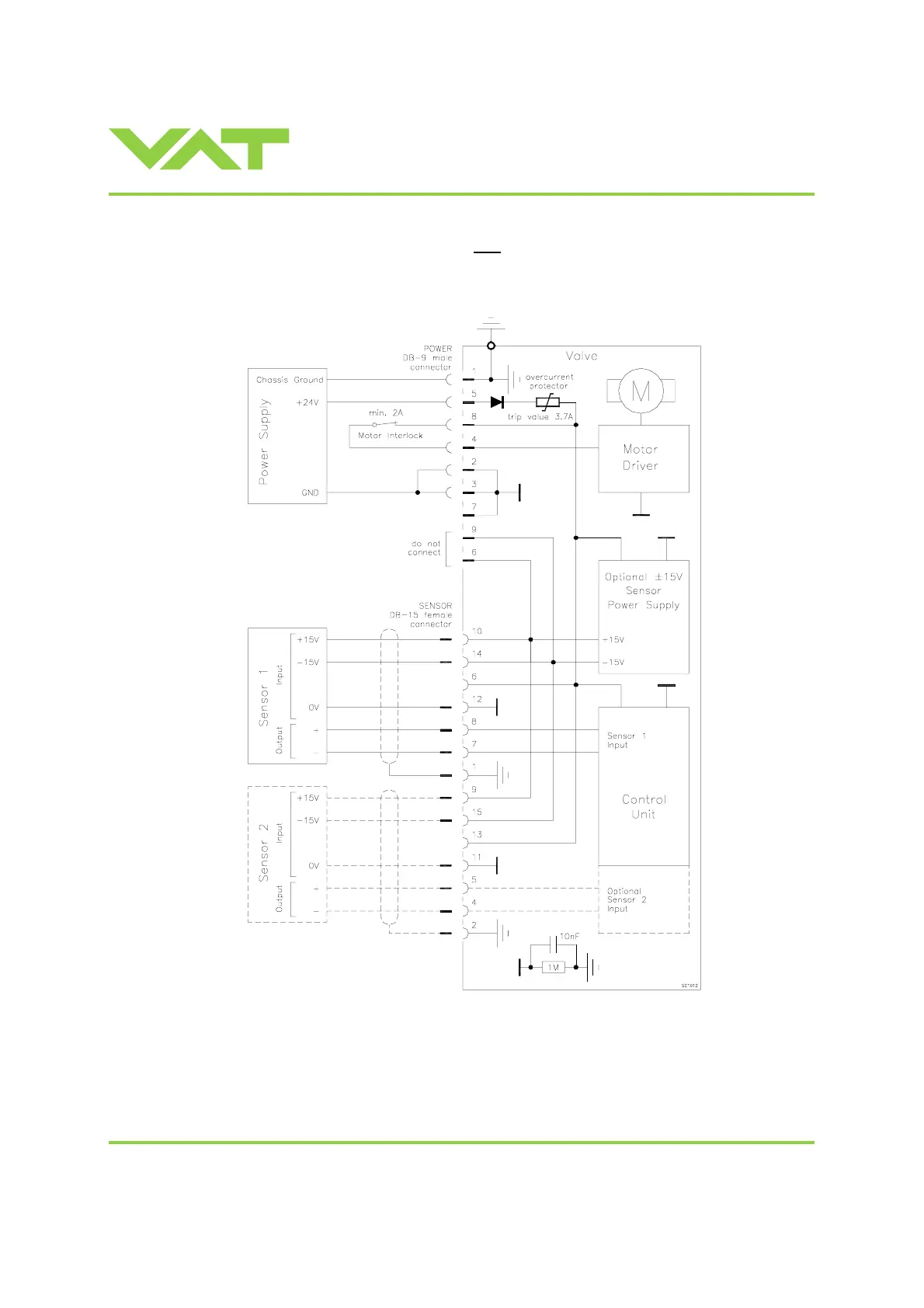
2.6.5 Power and sensor connection (±15 VDC sensors) with optional SPS module
[650 . . - . . V . - . . . . / 650 . . - . . W . - . . . . versions only]
Note:
• Use shielded sensor cable(s). Keep cable as short as possible, but locate it away from noise sources.
• Connect the ±15 VDC sensors at DB–15 female sensor connector exactly as shown in the drawing above.
Do not connect other pins, that may damage power supply or controller!
• Connector: Use only screws with 4-40UNC thread for fastening the connectors!
Low range sensor may be connected
to sensor 1 or sensor 2 input.
Do configuration accordingly.
Pins 4 and 8 must be bridged for operation!
An optional switch would allow for motor interlock
to prevent valve from moving.

 Loading...


