Installation, Operating & Maintenance Instructions
Series 650 DN 100-250 (I.D. 4“ - 10”), CC-Link
VAT Vakuumventile AG, CH-9469 Haag, Switzerland
Tel +41 81 771 61 61 Fax +41 81 771 48 30 CH@vatvalve.com www.vatvalve.com
280672EB
2010-12-15
65/94
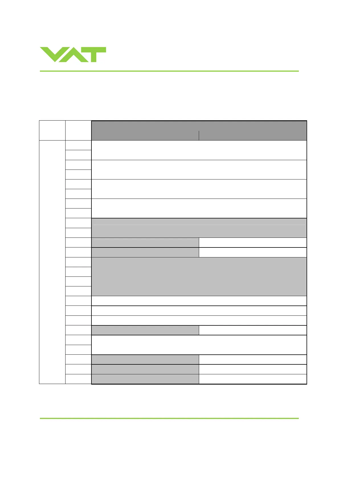
3.11.8 INPUT Buffer (Master PLC)
3.11.8.1 Overview
Buffer
Data
model
Index
Contents (MSB) Contents (LSB)
0
1
Pressure
2
3
Pressure Sensor 1
4
5
Pressure Sensor 2 (optional, only in case of 2 sensor version)
6
7
Position
8
9
Not used – reserved
10
Not used – reserved
Control mode
11
Not used – reserved
Fatal error
12
13
14
15
Not used – reserved
16 General status
17 General warnings
18 Extended warnings
19
Not used – reserved
Cluster valve monitoring address
20
21
Cluster valve position
22
Not used – reserved
Cluster valve control mode
23
Not used – reserved
Cluster valve status
16-Bit
(Word)
24
Not used – reserved
Cluster valve warnings

 Loading...


