Installation, Operating & Maintenance Instructions
Series 650 DN 100-250 (I.D. 4“ - 10”), CC-Link
VAT Vakuumventile AG, CH-9469 Haag, Switzerland
Tel +41 81 771 61 61 Fax +41 81 771 48 30 CH@vatvalve.com www.vatvalve.com
280672EB
2010-12-15
73/94
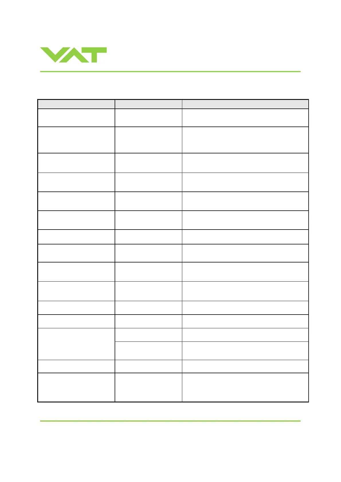
4 Trouble shooting
Failure Check Action
No dots lighted on display 24 V power supply ok?
Connect valve to power supply according to
«Electrical connection» and make sure that power supply is
working.
- Local operation via service
port active
- Switch to remote operation.
Remote operation does not work
- Safety mode active, check for
D on display?
- Provide power to motor to allow for operation.
- Refer to «Electrical connection» for details.
Display shows «E 20»
(fatal error - limit stop of valve unit
not detected)
- Replace actuator according to
«Maintenance procedures».
Display shows «E 21»
(fatal error - rotation angle of valve
plate limited during power up)
- Valve plate mechanically
obstructed?
- Resolve obstruction.
Display shows «E 22»
(fatal error - rotation angle of valve
plate limited during operation)
- Valve plate mechanically
obstructed?
- Resolve obstruction.
Display shows «E 40»
(fatal error - motor driver failure
detected)
- Replace control unit according to
«Maintenance procedures».
Display shows «D C» or «D999»
Motor Interlock is open
- Motor power supplied? - Provide power to motor to allow for operation.
- Refer to «Electrical connection» for details.
Display shows «SR»
(Service Request)
- Valve unit heavy
contaminated or gate seal
heavily sticking?
- Clean valve and/or replace gate seal according to
«Maintenance procedures».
CLOSE VALVE does not work
- Safety mode active, check for
D on display?
- Maintenance mode active
- Provide power to motor to allow for operation.
- Refer to «Electrical connection» for details.
- Refer to “Display shows «M C»” in this table
OPEN VALVE does not work
- Safety mode active, check for
D on display?
- Maintenance mode active
- Provide power to motor to allow for operation.
- Refer to «Electrical connection» for details.
- Refer to “Display shows «M100»” in this table
Display shows «M C»
Maintenance mode active
- Pin 14 of service connector is connected to ground. Plate
will close. Further movement of plate is blocked.
1)
Display shows «M100»
Maintenance mode active
- Pin 13 of service connector is connected to ground. Plate
will open. Further movement of plate is blocked.
1)
- Safety mode active, check for
D on display?
- Provide power to motor to allow for operation.
- Refer to «Electrical connection» for details.
POSITION CONTROL does not
work
- POSITION CONTROL
selected, check for V on
display?
- Select POSITION CONTROL mode.
Refer to «Position control» for details.
COMPRESSED AIR FAILURE
«AIRf»
- No or too less air pressure on
air input of valve
- Connect air or increase air pressure. Make sure that the air
pressure is more than 4 bar (55 psi).
COMPRESSED AIR FAILURE at
Exhaust «AIRx»
- Wrong connection of
compressed air input and
output
- No compressed air at output
exhaust
- Connect compressed air in accordance chapter installation.
- Contact your local VAT service centre for support.
1) Priority of pin 14 is higher than pin 13. If pin 14 is connected to ground after pin 13 the valve will close.
Ground of service connector is at pin 4 and 8.

 Loading...


