on the Vathin medical trolley or the recommended screws for installation. The recommended
screw specifications are: screws with a maximum depth of 6mm
Ensure sufficient power capacity and stable power supply before use. Severe fluctuations in
power supply must be regulated using a power regulator or UPS power supply.
If the loss of power leads to an unacceptable risk, the equipment should be connected to a
suitable external power source.
Caution
Always place the power cable in a place where it is unlikely to be stepped on. Do not place any
objects on the power cable.
Do not install the device in a place where it is difficult to disconnect from the power supply.
Before using this product for the first time, please refer to the product manual and follow the steps
below to install the product.
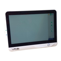
5.2.1 Open the stand of Digital Video Monitor and place it on a stable plane. Do not place the Digital
Video Monitor in a place where it is difficult to operate the disconnection device from the mains.
If necessary, connect the supplied Wi-Fi /LAN antenna to the Digital Video Monitor. Go to Appendix 3.
Cybersecurity and ensure that the use of the Digital Video Monitor's software and connectivity is
aligned with your organization's policies.
5.2.2 Connect the power cable to the power adapter and connect the power adapter to the power port
of the the Digital Video Monitor.
5.2.3 Connect the power cable to supply mains with protective earth. The power supply should be
stable. In case of severe fluctuations in the power supply, a power regulator or UPS power supply
should be used for adjustment purposes.
5.2.4 Connect the Digital Video Monitor to a medical display or digital video recorder or digital filing
system as needed.The digital filing system is a digital video recorder or hospital image storage
workstation (such as HIS, PACS system), which can be connected to the endoscopic image processor
through HDMI cable, SDI cable, or HDMI to DVI cable.
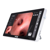
5.2.5 Connect the endoscope to the Digital Video Monitor by inserting the endoscope connector into
the endoscope socket properly as indicated by the arrow.
5.3. Switching On and Setup
Warning
When the device is turned on and the battery level is normal, the power switch indicator light is
green; When the device battery level is low, the power switch indicator light turns orange.