EMR3 Truck Installation Installation Procedures - Fuel Oil Truck Application
11
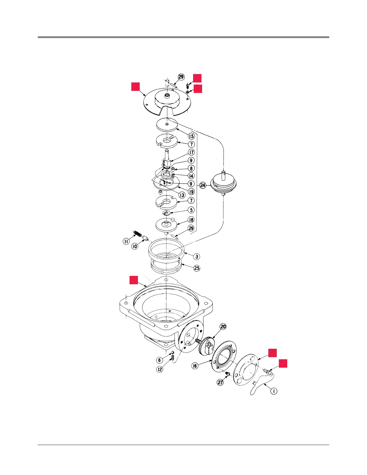
Figure 7. Disassembling the Tokheim Daniels, & Donovan calibrator
22
23
4
28
26
21
Disassemble the Tokheim
calibrator and keep parts
4, 21, 22, 23, 26, and 28
(items in square blocks)
emr\tok1.eps

 Loading...


