EMR3 Truck Installation Neptune Flow Meter Installation
18
Neptune Flow Meter Installation
Follow the installation procedures for your particular EMR
3
approved Flow Meter Installation.
NEPTUNE FLOW METER WITH TEMPERATURE COMPENSATION
NEPTUNE FLOW METER WITHOUT TEMPERATURE COMPENSATION
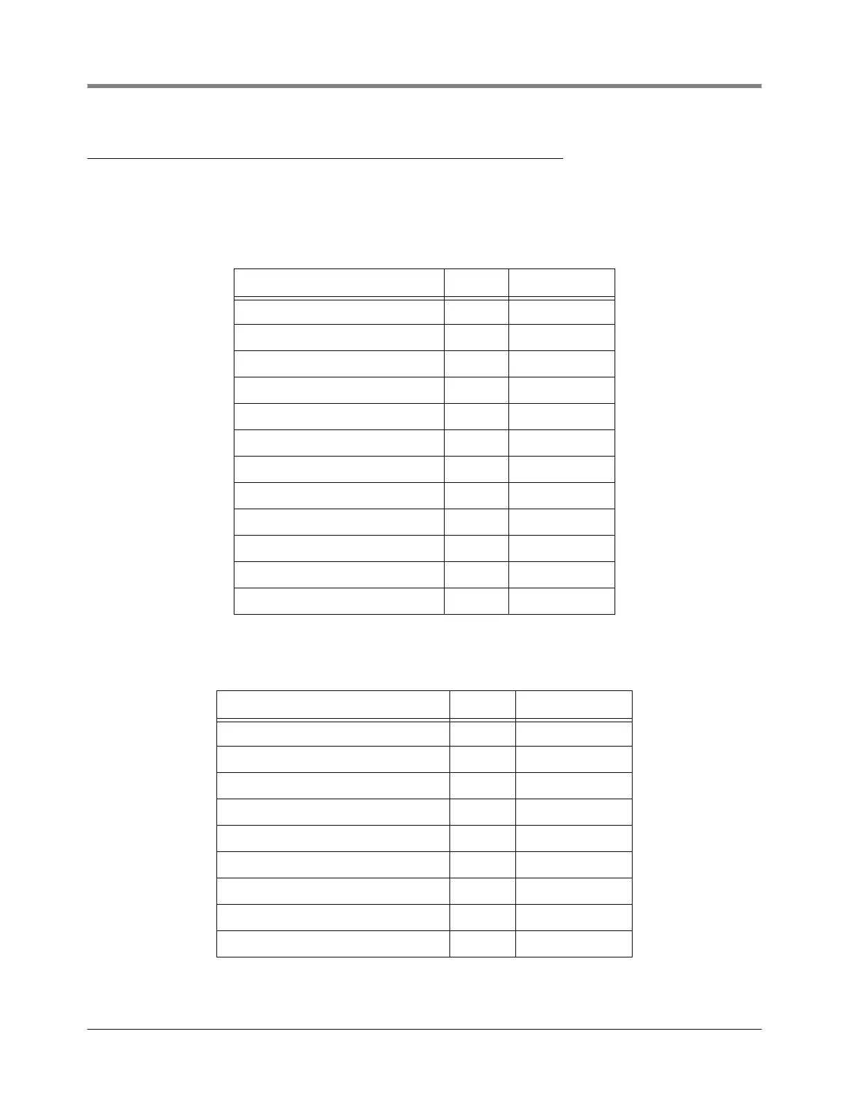
Table 5.- Display Head-to-Neptune With Temp. Comp. Adaptor Kit 846000-008
Item Qty V-R P/N
Neptune Adaptor Ring 1 328159-003
Input Shaft 1 331656-001
Screws - 1/4-20 x 3/4” 4 510500-325
Screws - 1/4-20 x 5/8” 4 503615-001
Seal Wire 1 011853-285
Groove Pin 1 510107-002
Lockwashers 8 510003-006
Washer - 0.010” thick 1 011071-929
Washer - 0.005” thick 1 011071-785
Truarc Retaining Ring 1 511816-001
Coupling 1 323372-001
Groove Pin 1 510107-002
Table 6.- Display Head-to-Neptune W/o Temp. Compensation Adaptor Kit 846000-009
Item Qty V-R P/N
Neptune Spacer 1 323672-001
Stud 2 036788-005
Lockwasher 2 510023-001
Nut 2 511041-001
Screw-Seal (Meter Register Mounting) 4 503615-001
Lockwasher 4 510003-006
Seal Wire 1 011853-285
Coupling Group (w/Groove Pin) 1 323372-001
Groove Pin 1 510107-002

 Loading...


