EMR3 Truck Installation Installing the Printer (Optional)
36
*Use Loctite® 243 Threadlocker® on all printer stand mounting bolts. (Loctite and 243 Threadlocker are registered
trademarks of Loctite Corporation.)
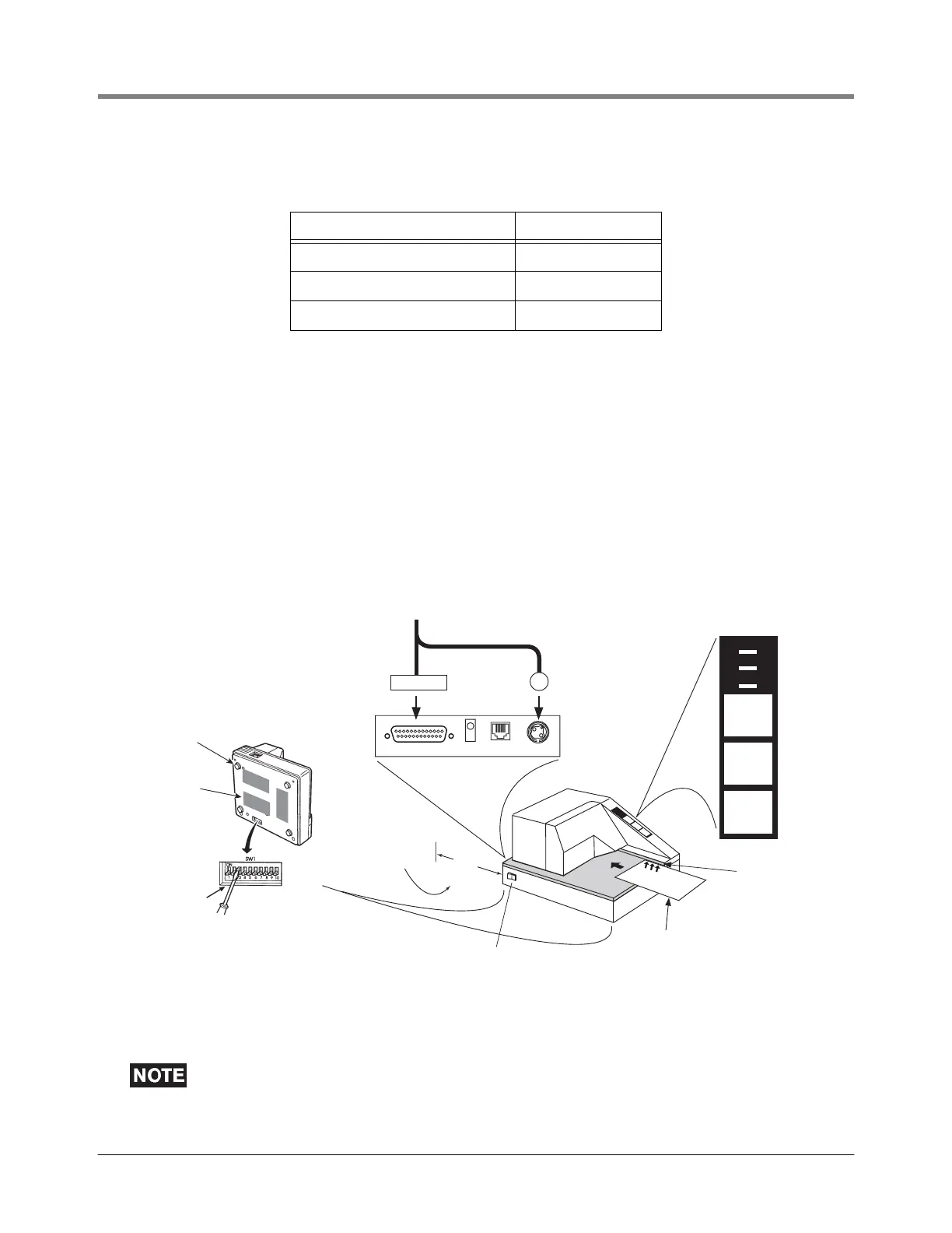
A power/data cable and three 2” x 3” (50 x 75 mm) Velcro strips are included in the printer kit. Figure 27 shows
the front panel lights and controls, and the rear panel connections to the TM-295 Slip printer and illustrates the
TM-295 printer’s address code setup for DIP switch 3 (which must be set as shown or it will not work) and
suggested positions for the Velcro strips. Remove the rubber feet from the base of the printer to permit maximum
contact between the Velcro strips and the mounting plate.
Attach the four wires of the printer power/data cable to the appropriate terminals of the Power Side terminal block
in the IB (Figure 22 on page 30) and the DB-25 connector and the round power connector to the appropriate
connectors on the rear of the printer.
Figure 27. TM-295 printer
The printer ribbon should be removed if using “carbonless forms”. Power to the printer is re-
quired to release the carriage and install/remove a printer ribbon.
Table 11.- Low-Cab Installation*
Item SMC P/N
Base plate ZPLT-1
Pillar stack PS12-A
Removable platform VMI-L0
POWER
RELEASE
PAPEROUT
REVERSE
FORWARD
RELEASE
RS-232 FG D.K.D. POWER
Rear
Connector
Panel
Front Panel Lights
and Controls
emr\print.eps
Power On/Off
Switch
Connect round
power connector
to power port
Connect DB-25
data connector
to RS-232 port
Cable from the IB unit
(V-R # 331791-001)
Slide ticket in face up keeping right side of
ticket against print guide. Push in ticket
as far as it will go. Press the FORWARD ke
until the PAPER OUT light turns off.
Print guide
2.5"
(63.5 mm)
Connector
clearance
Set Pole 3 of
DIP switch ON
ttach the 3 velcro
trips to the bottom
plate of the printer
Scrape off the
4 rubber pads
from the printer's
base

 Loading...


