EMR3 Truck Installation Neptune Flow Meter Installation
20
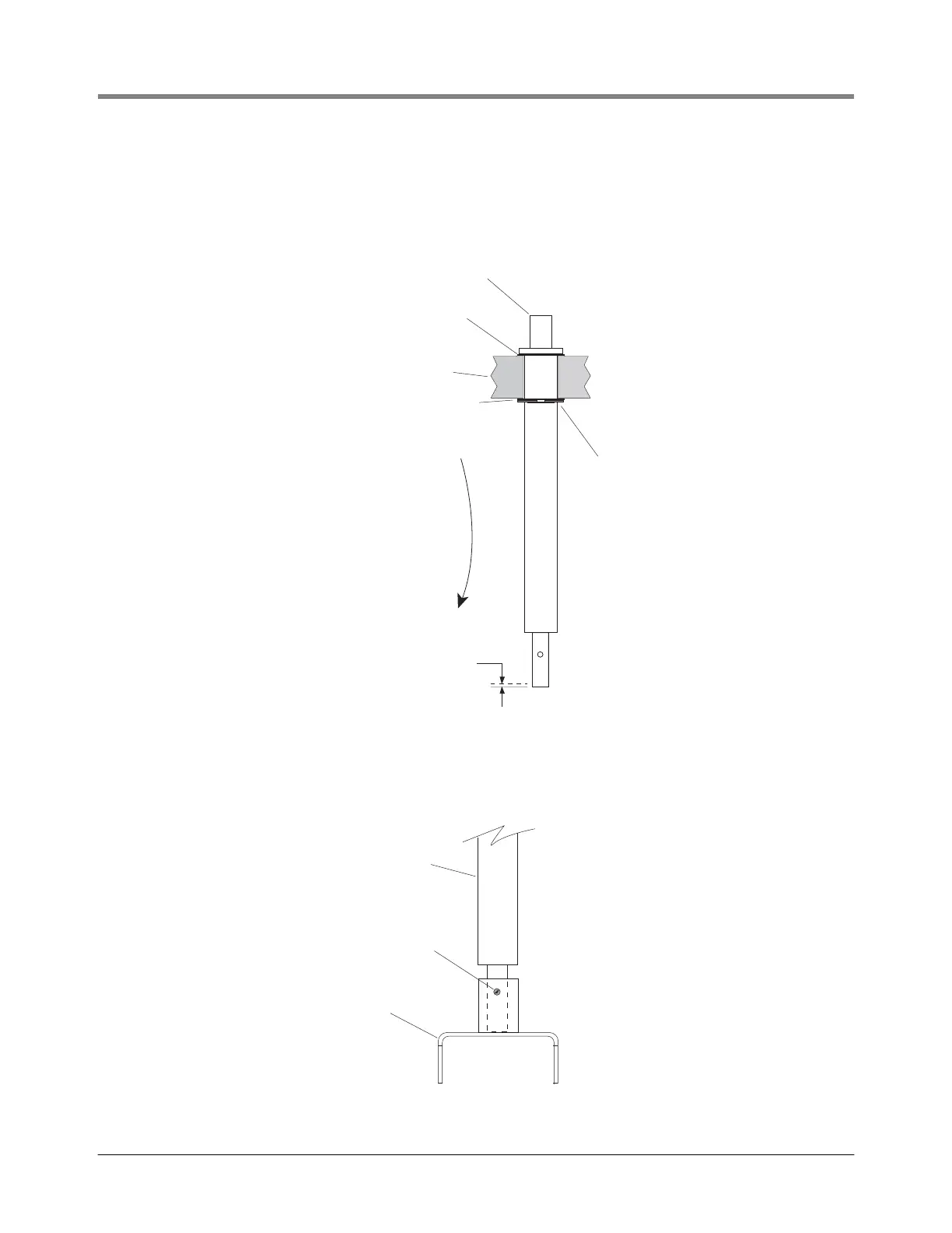
12. Get the 4” (101.60 mm) long input shaft, the 0.10” and 0.005” thick washers, the retaining ring, the groove
pin, and the coupling from the installation kit. Assemble the new shaft, the 0.10” washer you removed from the
Display Head shaft in the previous step, the 0.005” washer, and the retaining ring in the Display Head base as
shown in Figure 15. If the 0.10 - 0.015” endplay is exceeded, remove the retaining ring and replace the
0.005” washer with the 0.010” washer.
Figure 15. Assembling Neptune adaptor shaft group to Display Head
13. With the end play within limits, get the coupling and groove pin from the kit and attach the coupling to the
bottom of the input shaft with the pin as shown in Figure 16.
Figure 16. Attaching coupling to Neptune adaptor shaft
EMR Base
0.010" (0.25 mm)
Washer -reused
0.005" (0.127 mm) washer
from kit (if necessary use
0.10" washer from kit instead
to get desired end play)
Retaining rin
from kit
0.10 - 0.15"
(0.25 - 0.38 mm)
endplay
Input shaft 4" (101.6 mm) long from kit
emr/nepshft.eps
Groove pin
from kit
Input shaft
oupling
rom kit
emr/nepcou.ep

 Loading...


