18
4 Mounting
VEGAPULS 63 • Modbus and Levelmaster protocol
41364-EN-170711
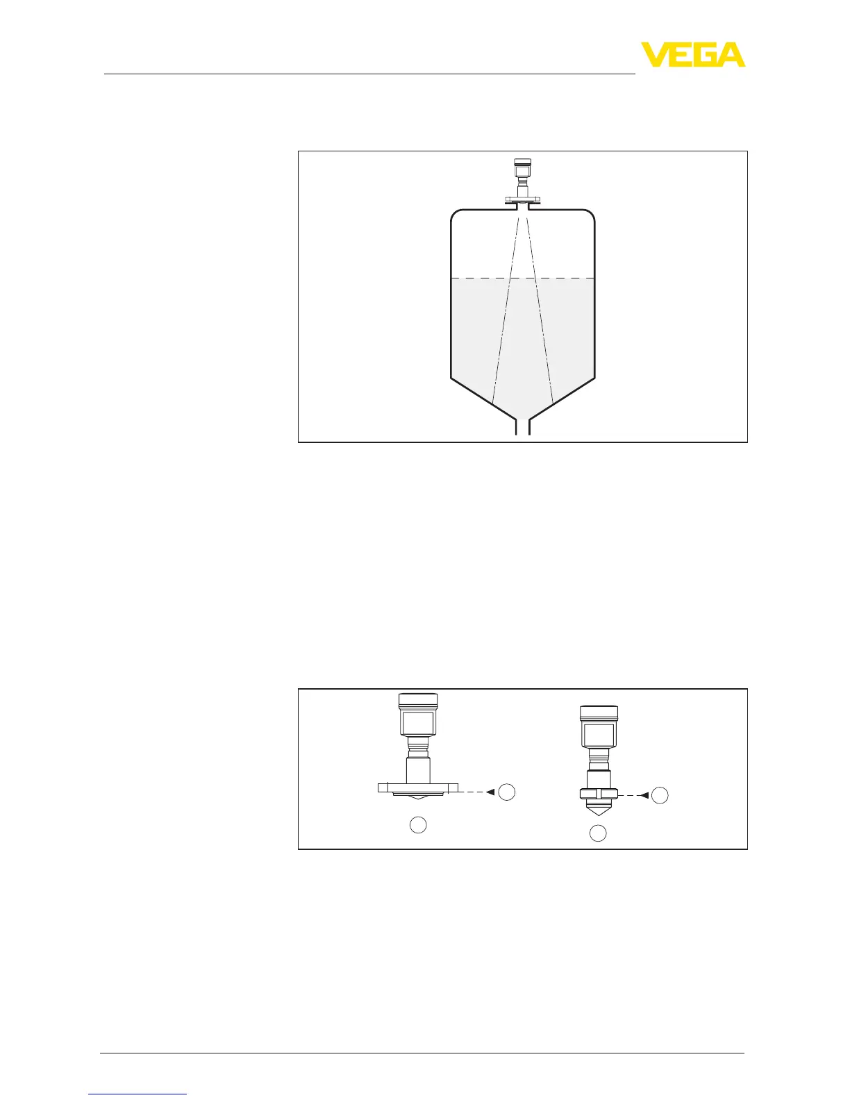
In vessels with conical bottom it can be advantageous to mount the
sensor in the centre of the vessel, as measurement is then possible
down to the bottom.
Fig. 6: Mounting of the radar sensor on vessels with conical bottom
The measuring range of VEGAPULS 63 begins physically at the end
of the antenna; the adjustment, however, begins at the reference
plane.Thereferenceplaneisdierentdependingonthesensorver-
sion.
•
Flange with encapsulated antenna system: The reference
planeistheloweredgeoftheange
•
Hygienicttings: The reference plane is the highest contact point
betweensensorprocessttingandweldedsocket
The following graphic shows the position of the reference plane with
dierentsensorversions.
1
1
3
2
Fig. 7: Position of the reference plane
1 Reference plane
2 Flange connections
3 Hygienicttings
Donotmounttheinstrumentsinorabovethellingstream.Makesure
thatyoudetecttheproductsurface,nottheinowingproduct.
Reference plane
Inowingmedium






 To Next Page