20
4 Mounting
VEGAPULS 63 • Modbus and Levelmaster protocol
41364-EN-170711
Socket diameter d Socket length h
150 mm ≤500mm
Socket diameter d Socket length h
2"
≤3.9in
3" ≤11.8in
4" ≤15.8in
6" ≤19.7in
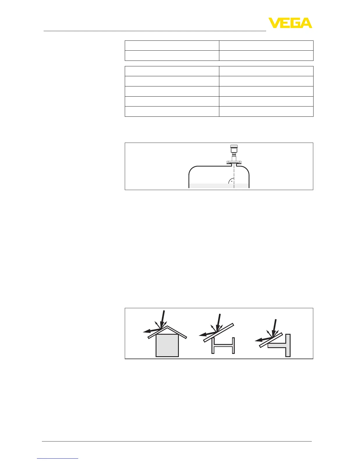
In liquids, direct the sensor as perpendicular as possible to the prod-
uct surface to an achieve optimum measurement.
Fig. 10: Alignment in liquids
The mounting location of the radar sensor should be a place where no
otherequipmentorxturescrossthepathoftheradarsignals.
Vessel installations, such as e.g. ladders, limit switches, heating spi-
rals, struts, etc., can cause false echoes and impair the useful echo.
Make sure when planning your measuring point that the radar sensor
has a "clear view" to the measured product.
In case of existing vessel installations, a false signal suppression
should be carried out during setup.
If large vessel installations such as struts or supports cause false
echoes, these can be attenuated through supplementary measures.
Small,inclinedsheetmetalbaesabovetheinstallationsscatterthe
radarsignalsandpreventdirectinterferingreections.
Fig.11:Coverat,large-areaproleswithdeectors
If there are agitators in the vessel, a false signal suppression should
be carried out with the agitators in motion. This ensures that the
interferingreectionsfromtheagitatorsaresavedwiththebladesin
dierentpositions.
Sensor orientation
Vessel installations
Agitators





 To Next Page