23
4 Mounting
VEGAPULS 63 • Modbus and Levelmaster protocol
41364-EN-170711
ø 60,3 mm
(2.37")
ø 88,9 mm
(3.5")
d x 2
26 mm
(1.02")
15 mm
(0.59")
2 mm
(0.08")
2 mm
(0.08")
5 mm
(0.20")
4 mm
(0.16")
80 mm
(3.15")
80 mm
(3.15")
75°
4 mm
(0.16")
8 mm
(0.32")
75°
4 mm
(0.16")
8 mm
(0.32")
d x 2
ø 88,9 mm
(3.5")
ø 60,3 mm
(2.37")
11
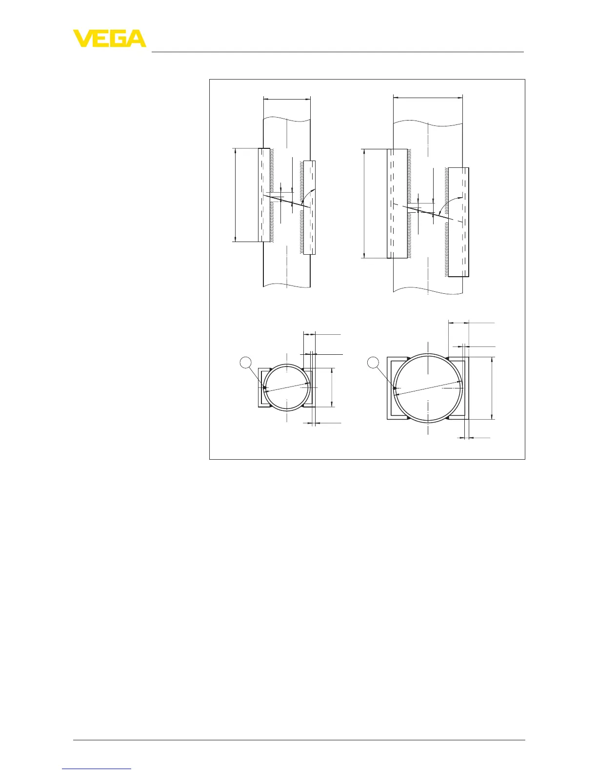
Fig.14:Weldingconnectionwithsurgepipeextensionfordierentexample
diameters
1 Position of the welded joint with longitudinally welded pipes
Instructions of orientation of the polarisation:
•
Note marking of the polarisation on the sensor
•
Withthreadedversions,themarkingisonthehexagon,withange
versionsbetweentwoangeholes
•
The marking must be in one plane with the holes in the surge pipe
Instructions for the measurement:
•
The 100 % point must be below the upper vent hole and the
antenna edge
•
The 0 % point is the end of the surge pipe
•
During parameter adjustment, select "Application standpipe" and
enter the tube diameter to compensate for errors due to running
time shift
•
A false signal suppression with the installed sensor is recom-
mended but not mandatory
•
The measurement through a ball valve with unrestricted channel
is possible
Surge pipe extension
Instructions and requir
e-
ments, surge pipe





 To Next Page