OPERATIONAL CONTROLS
Operation - 28
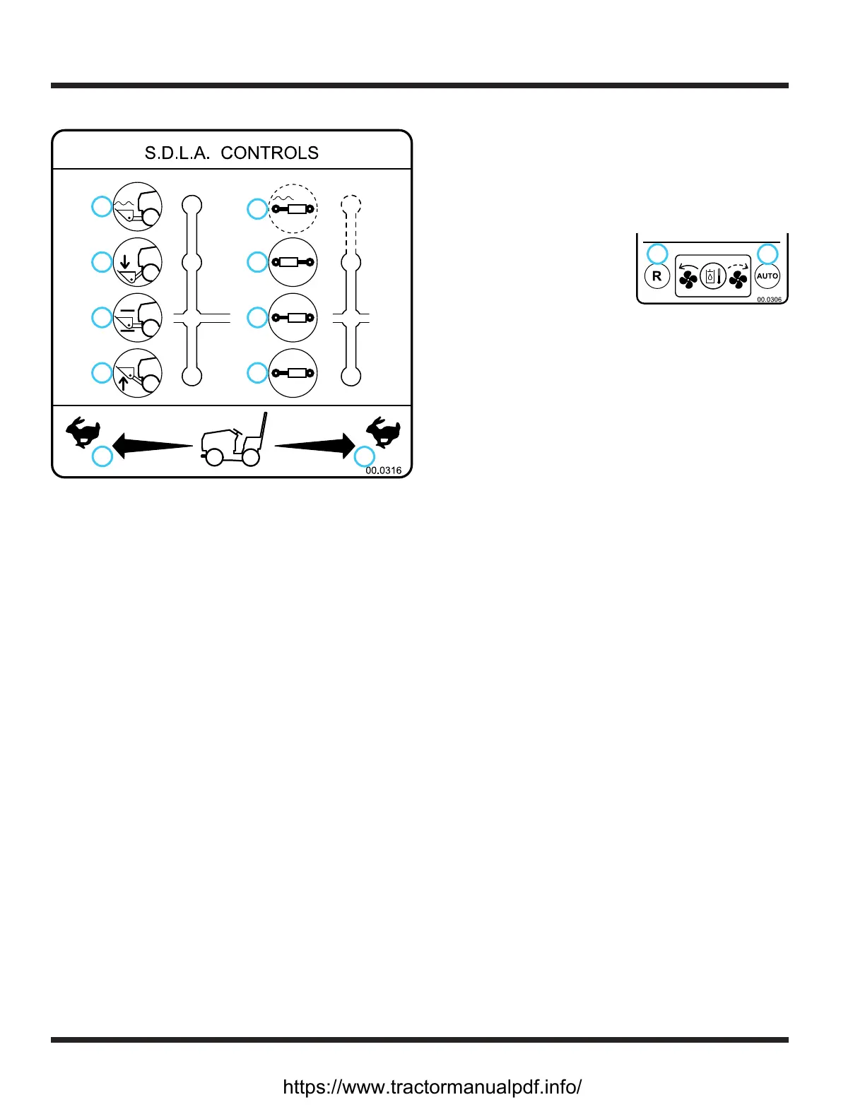
SDLA Control Lever (P & Q)
1
2
3
4
5
6
7
8
9
10
1. Forward Direction
2. Reverse Direction
3. Lift
4. Hold
5. Lower
6. Float
7. Direction #1
8. Hold
9. Direction #2
10. Float (if equipped)
The SDLA (Speed, Direction, Lift, & Auxiliary) is the
primary control for the power unit and consists of two
levers. The primary SDLA control lever (P) controls the
speed, the direction of travel, and the lift of the hitch
arms. The secondary SDLA control lever (Q) controls
the auxiliary hydraulic circuit.
S - Speed: the amount of forward or backward move-
ment of the primary SDLA lever controls the
ground speed of the power unit.
D - Direction: the forward or backward movement of
the primary SDLA lever controls the direction of
the power unit.
L - Lift: the lift function of the primary SDLA lever has
four positions: Up, Hold, Down, and Float Lock.
Hold is the default position and holds the hitch
arms from moving up or down. Pulling the lever
to the left raises the hitch arms. Pushing the lever
to the right lowers the hitch arms. Float position is
attained by pushing the lever to the right until the
oat detent engages and locks the lever in place.
A - Auxiliary: the left or right movement of the second-
ary SDLA lever controls the functions of the attach-
ments that require the auxiliary hydraulic circuit.
An optional oat kit (part # 23.0111-7) is available
for the auxiliary hydraulic circuit.
Steering Wheel (R)
Turn the steering wheel to the left (counterclockwise)
to turn the power unit to the left. Turn the steering
wheel to the right (clockwise) to turn the power unit
to the right.
Hydraulic Cooler Fan Switch (S)
The hydraulic oil cooler
1
2
fan switch is normally set to
the automatic thermostati-
cally controlled position (1).
This allows the thermostat to
turn on the cooling fan when the hydraulic uid
reaches the set temperature. The fan pulls air through
the right fender next to the operator, through the oil
cooler, and discharges the air out the back of the
power unit.
The switch can be set to the reverse position (2) to pull
air from the rear of the power unit, through the oil
cooler, and discharge the warm air next to the opera-
tor. This feature can be used to help provide warmth
for the operator during cold weather.
Seat Slide Lever (T)
Move the seat slide lever to the left to release the seat
lock. Move the seat forward or backward to the de-
sired position and release the seat slide lever to lock
the seat in place.
https://www.tractormanualpdf.info/