SERVICE
Service - 68
Neutral Switch Adjustment
WARNING
An improperly adjusted neutral switch can result in
erratic engine cranking or unsafe power unit move-
ment. Check the neutral switch position after any
adjustment is made to the neutral position.
1. Park the power unit on a level surface.
WARNING
The parking brake must be disengaged as part of
the adjustment procedure. Park the power unit on
a level surface and place wheel chocks in front and
back of the wheels to prevent the power unit from
rolling forward or backward.
2. Place wheel chocks in front and back of the
wheels to prevent accidental movement.
3. Remove the pump cover from the power unit.
4. Disengage the parking brake.
5. Turn the ignition key to the Run position to acti-
vate the electrical system, but do not start the
engine.
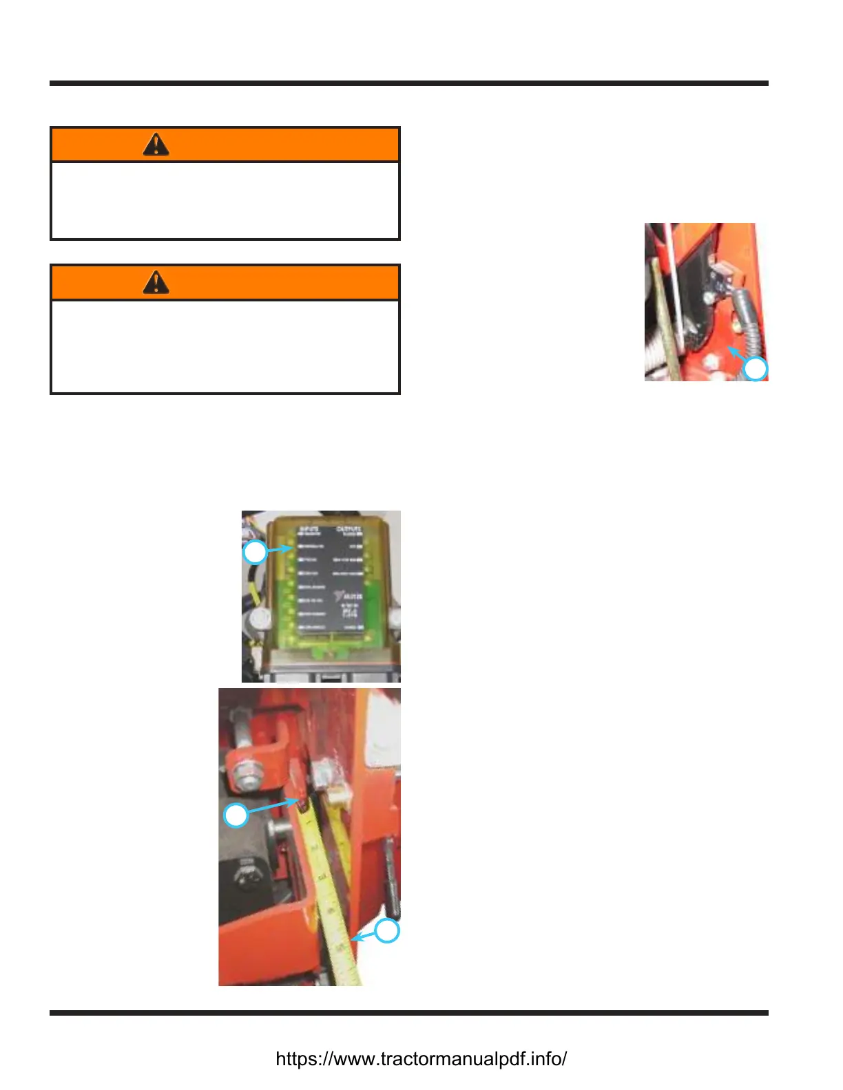
A
6. Locate the tractor con-
trol module (TCM) under
the power unit’s hood.
The neutral switch input
light (A) will be used as
an indicator for when
the neutral switch is on
or o.
7.
C
B
Measure and record the
distance between the
front frame (B) and
the pump arm (C).
8. Move the SDLA lever
slowly in the forward
direction while
watching the neutral
switch input light.
When the light turns
o, stop the SDLA
lever and measure
the distance between
the front frame and
the pump arm. This
measurement should
be a minimum of .8
mm (1/32 inch) less
and a maximum of
1.6 mm (1/16 inch)
less than the measurement taken when the SDLA
lever was at the neutral position. (e.g., if the
original measurement was 101.6 mm (4 inches)
the measurement when the neutral switch input
light turns o must be between 100.8 mm (3-
31/32 inch) and 100 mm (3-15/16 inch). NOTE: it is
helpful to have an assistant to take the measure-
ments.
D
9. If the measurement is not
within the specied range, ad-
just the neutral switch mount
(D) by loosening the two
mounting bolts and sliding
the mount in the necessary
direction. Tighten the switch
mount hardware to 11 Nm
(100 in-lbs).
10. Repeat steps 8 and 9 as needed until the mea-
surement is within the specied range.
11. Turn the ignition key to the o position.
12. Engage the parking brake.
13. Reinstall the pump cover.
14. Remove the wheel chocks.
15. If you are unsure of the correct procedure to
adjust the neutral switch, or if you are unable to
attain the correct setting, contact on authorized
Ventrac dealer for assistance.
https://www.tractormanualpdf.info/