OPERATIONAL CONTROLS
Operation - 30
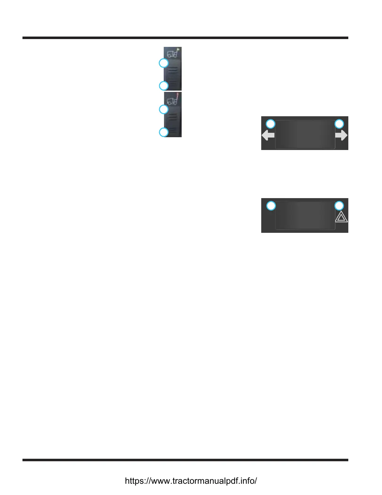
Work Light Switch (AA)
1
2
Press the top (1) of the work light switch to
turn on the work lights. Press the bottom (2)
of the switch to turn the work lights o.
Strobe Light Switch (BB)
1
2
Press the top (1) of the strobe light switch to
turn on the strobe light. Press the bottom (2)
of the switch to turn the strobe light o.
Slope Indicator Gauge (CC)
The 70.4112 digital slope indicator gauge works with
a bidirectional slope meter to display the angle of a
slope in degrees. NOTE: sudden changes in speed or
direction may aect the slope value displayed.
The 70.4140 slope indicator gauge is designed to moni-
tor the total slope angle of the terrain where the power
unit is operating. Total slope angle combines side-to-
side angle with front-to-back angle to provide a true
overall measurement of slope angle, regardless of the
power unit orientation. The slope gauge has slope limit
set-points that can be changed to match the capability
of the power unit conguration along with attachments
that might limit the slope rating of the power unit. The
slope gauge is equipped with both audible and visual
alerts which can be set independently to warn the
operator of limiting conditions. The display screen has
multiple options to suit the operator preference.
Refer to the Slope Gauge Settings and Operation
section for calibration, settings, and operation instruc-
tions.
Slope Warning Light (DD)
The slope warning light works with the 70.4112 slope
indicator system to provide a visual warning when the
slope value exceeds 20 degrees.
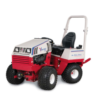
Directional Signal Switch (EE)
Press the left
1 2
side (1) of the directional signal switch to
turn on the left turn
signal. Press the right
side (2) of the direc-
tional signal switch to
turn on the right turn
signal. Return the switch to the middle position to
turn o the signals. The left and right turn signals will
override the hazard ashers.
Hazard Flasher Switch (FF)
Pressing the right
2 1
side (1) of the hazard asher switch
ashes both of the
directional turn signal
lights. Press the left
side (2) of the switch to
turn the hazard asher
lights o. Use of the directional turn signals will over-
ride the hazard ashers until the turn signal is turned
o.
Horn Switch (GG)
Press the horn switch to sound the signal horn. The
horn will sound until the horn switch is released.
https://www.tractormanualpdf.info/