Troubleshooting - 75
TROUBLESHOOTING
Electrical Troubleshooting Using the Trac-
tor Control Module (TCM)
The TCM monitors the electronic circuits necessary for
the engine, the starter, and the PTO to function. These
input circuits include the PTO switch, the neutral
switch, the parking brake switch, the ignition switch,
and the generator presence. The TCM is programmed
to allow the engine, the starter, and the PTO to oper-
ate only when specic input criteria are satised. The
engine, the starter, and the PTO circuits are controlled
by outputs from the TCM.
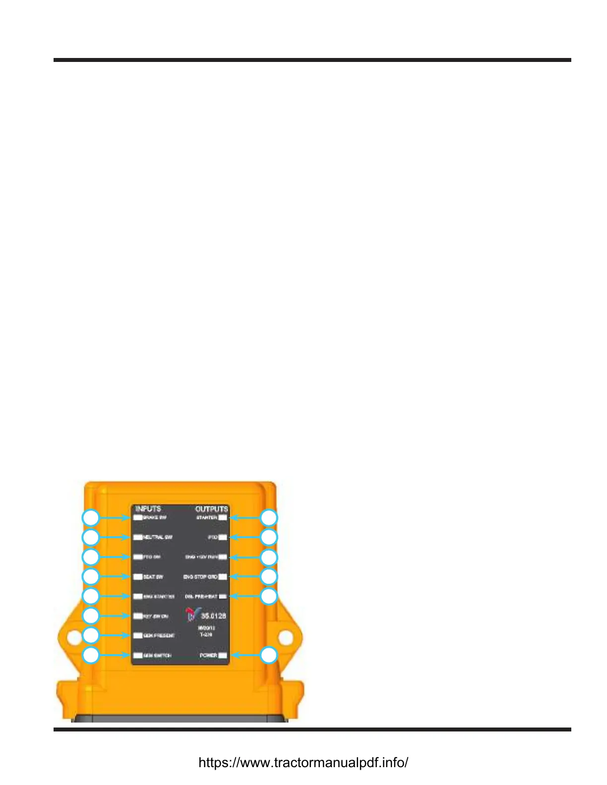
For troubleshooting purposes, the TCM includes red
LED lights for each circuit. The LED lights will activate
when the input or output circuit is activated. The
TCM is divided into two sections: the left (input) side
displays the eight inputs with red LED lights and the
right (output) side displays the ve outputs, also with
red LED lights. The TCM has two power supplies. The
rst supplies power to the computer independent of
the ignition switch so that the TCM does not turn on
and o with each ignition switch cycle. (NOTE: when
the battery disconnect switch is turned o, the TCM is
also turned o). The second supply energizes the rest
of the computer when the ignition switch is turned
on.
When the battery disconnect switch is turned on, the
Power LED light (J) will illuminate. If the system
voltage drops below a preset value when the ignition
switch is o, or if the power unit sits unused for more
than fteen days, the TCM will automatically go into
Sleep mode and enter a reduced power state. To wake
the TCM, turn the battery disconnect switch o for ten
seconds and then turn back on.
A
B
C
D
E
F
G
H J
K
L
M
N
O
Input Circuits
Brake Switch (A)
The light indicates the circuit is closed and the park-
ing brake is engaged. In order for this light to oper-
ate, the key must be turned to the run position.
Neutral Switch (B)
The light indicates the circuit is closed and the
power unit’s SDLA control lever is in neutral. In or-
der for this light to operate, the key must be turned
to the run position and the SDLA lever must be in
the neutral position.
PTO Switch (C)
The light indicates the PTO switch is in the On posi-
tion. In order for this light to operate, the key must
be turned to the run position and the PTO switch
must be in the On (engaged) position.
Seat Switch (D)
The light indicates that an operator is present in the
seat. In order for this light to operate, the key must
be turned to the run position and the operator must
be present in the seat.
Engine Starter (E)
The light indicates that the key is turned to the start
position.
Key Switch On (F)
The light indicates that the key is turned to the run
(on) position. The key must be turned to the run
position for the TCM to activate.
Generator Present (G)
The light indicates that the generator is connected
to the power unit, which activates a specic set
of criteria and allows the PTO to operate without
an operator present on the seat. In order for this
light to operate, the key must be turned to the run
position and a generator must be connected to the
power unit.
Generator Switch (H)
The light indicates that the switch on the genera-
tor is set to the On (engaged) position. In order for
this light to operate, the key must be turned to the
run position, a generator must be connected to the
power unit, and the switch on the generator must
be pulled up to the On position.
https://www.tractormanualpdf.info/