10
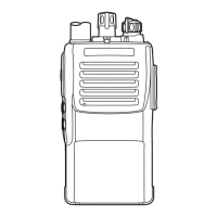
Side A
Alignment
The transceiver must be programmed for use in the
intended system before alignment is attempted. The RF
parameters are loaded from the file during the alignment
process.
In order to facilitate alignment over the complete op-
erating rang of the equipment, it is recommended that the
channel data in the transceiver be preset as per the chart
below.
Set up the test equipment as shown below for trans-
ceiver alignment, and apply 7.5V DC power to the trans-
ceiver.
PLL VCV (Varactor Control Voltage)
Connect the DC voltmeter between TP2045 on the
Main Unit and ground.
Set the transceiver to CH 4 (high band edge), and ad-
just L2036 on the Main Unit for 4.0 V ± 0.1 V on the
DC voltmeter.
Set the transceiver to CH 3 (low band edge), and con-
firm the low-end VCV is more than 0.9 V while re-
ceiving.
Set the transceiver to CH 4 (high band edge), and ad-
just L2038 on the Main Unit for 4.0 V ± 0.1 V while
transmitting.
Set the transceiver to CH 3 (low band edge), and con-
firm the low-end VCV is more than 0.9 V while trans-
mitting.
CLONE GND
SP MIC IN
Transceiver
Power Supply
7.5 VDC
Radio
Tester
Adapter
MIC/SP
COM Port
ANT
RF IN/OUT
MIC
AF OUT
AF IN
SP CLONE
CLONE CT-29
AF OUT
AF IN
SP
MIC IN
10µF/16V
PTT
2.2 k
Ω
4
Ω
FREQUENCY
(
SIMPLEX
)
160.100 MHz
160.100 MHz
146.100 MHz
173.900 MHz
CHANNEL
CH 1
CH 2
CH 3
CH 4
CHANNEL SPACE
Wide
Narrow
Wide
Wide
Side B
TP2045
L2038
L2036
 Loading...