Do you have a question about the Vertex Standard VX-424A Series and is the answer not in the manual?
| Brand | Vertex Standard |
|---|---|
| Model | VX-424A Series |
| Category | Transceiver |
| Language | English |
Expertise needed for surface-mount components; risks for unauthorized servicing and potential legal issues.
Explains diagrams for double-sided boards, referencing "leaded" or "chip-only" sides.
Transceiver uses lead-free solder; repairs must use lead-free solder for compliance.
Covers frequency, channels, voltage, temperature, dimensions, and weight.
Details sensitivity, selectivity, output power, modulation, and noise figures.
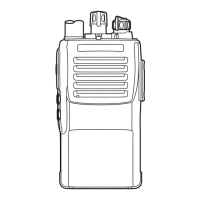
Details parts for the front case, including light guide, speaker, and keypad assembly.
Lists parts for the main unit, rear case, and terminal plates.
Shows the battery pack and belt clip assembly.
Illustrates the signal paths and components within the MAIN-2 unit.
Shows signal flow for transmit and receive functions, including VCO and PLL.
Details the RF signal path from antenna to audio output, including filters and mixers.
Explains how the squelch operates based on noise detection and microprocessor control.
Describes the audio signal path from microphone to RF output, including modulation and PLL.
Explains automatic transmit power control and transmitter inhibit logic.
Details the PLL circuitry for receive and transmit frequencies, including VCO and phase locking.
Explains how the PTT switch activates transmission and disables the receiver.
Lists required test equipment and software for alignment.
Outlines precautions like temperature control, dummy loads, and warming up equipment.
Instructions for connecting the CT-42 plug for programming, including removing the cap.
Describes test equipment setup and recommends programming channel data before alignment.
Details steps for adjusting the PLL VCV using TP2045, L2036, and L2038.
Instructions for installing the VX-424A Programming Software on a PC.
Steps to align the reference frequency using the software and a slide bar.
Steps to adjust high (5.0 W) and low (1.0 W) power outputs using the software's slide bar.
Adjusts maximum deviation for wide and narrow bands using a 2 kHz tone.
Adjusts CTCSS deviation for wide and narrow bands using a CTCSS test tone.
Adjusts modulation balance for wide and narrow bands, without microphone input.
Adjusts DCS deviation for wide and narrow bands using a DCS test tone.
Adjusts LTR deviation for wide and narrow bands using an LTR test tone.
Adjusts sequential tone deviation and standard deviation (MIC Gain).
Tunes receiver sensitivity and aligns the tight noise squelch level.
Aligns threshold noise squelch level and tight noise squelch RSSI.
Aligns tight noise squelch RSSI (wide) and threshold noise squelch (narrow).
Aligns TX Save RSSI for wide and narrow bands with specified output levels.
Completes the alignment routine by exiting the software and turning off the radio.
Illustrates the component placement on the MAIN-2 unit, Side A.
Illustrates the component placement on the MAIN-2 unit, Side B.
Lists capacitors (C2002-C2181) and diodes (D2001-D2050) with their specifications.
Lists resistors (R2002-R2345) and inductors (L2001-L2038) with their specifications.