13
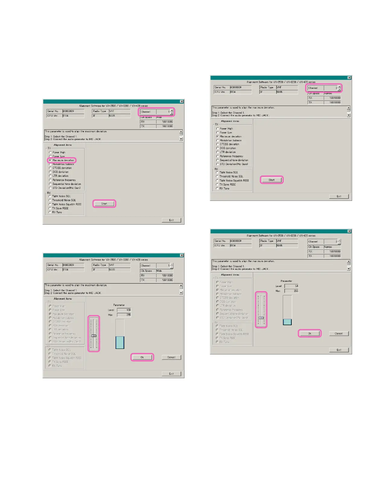
g Move the Slide Bar, as needed as, so that the deviation
meter reading is 4.2 kHz ± 0.1 kHz.
h Press the “OK” box to lock in the new data.
i Set the transceiver to CH 2 (band center, narrow de-
viation) via the “Channel” box on the “Alignment” win-
dow.
j Click the left mouse button on the “Start” button.
Max Deviation
c Set the transceiver to CH 1 (band center, wide devia-
tion) via the “Channel” box on the “Alignment” win-
dow previously.
d Inject a 2 kHz tone at 100 mVrms to the MIC jack.
e Click the left mouse button on the “Maximum Devia-
tion” button.
f Click the left mouse button on the “Start” button.
c
e
f
k Move the Slide Bar, as needed as, so that the deviation
meter reading is 2.1 kHz ± 0.1 kHz.
l Press the “OK” box to lock in the new data.
g
h
i
j
k
l
Alignment
 Loading...