1
Contents
Operating Manual Reprint ................................................................................................................................................ 2
Cloning ................................................................................................................................................................................ 10
Specifications ..................................................................................................................................................................... 11
Exploded View & Miscellaneous Parts ......................................................................................................................... 12
Block Diagram .................................................................................................................................................................... 13
Circuit Description ............................................................................................................................................................ 14
Alignment ........................................................................................................................................................................... 17
Test Adapter Schematic .................................................................................................................................................... 23
Board Units (Schematics, Layouts & Parts)
MAIN Unit ...................................................................................................................................................................... 25
VR Unit ............................................................................................................................................................................ 57
SW Unit ............................................................................................................................................................................ 58
Dummy Unit ................................................................................................................................................................... 59
Optional Board Units (Schematics, Layouts & Parts)
F2D-8 2-Tone Decode Unit............................................................................................................................................ 60
VTP-50 VX-Trunk Unit .................................................................................................................................................. 62
FVP-25 Encryption / DTMF Pager Unit ...................................................................................................................... 64
F5D-14 5-Tone Unit ........................................................................................................................................................ 66
©2007 VERTEX STANDARD CO., LTD. E014U95A
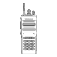
UHF Band
Service Manual
VX-600
Introduction
This manual describes the circuit theory, program-
ming procedures, and alignment procedures for the
UHF Portable Transceiver.
Much of the operating flexibility of the
is
derived from its versatile "Soft Key" front panel keys.
These keys may be configured for a number of op-
erating functions, as described in this manual.
Following the discussion of transceiver operation,
details regarding programming software, alignment,
and maintenance will follow.
VERTEX STANDARD CO., LTD.
4-8-8 Nakameguro, Meguro-Ku, Tokyo 153-8644, Japan
VERTEX STANDARD
US Headquarters
10900 Walker Street, Cypress, CA 90630, U.S.A.
YAESU EUROPE B.V.
P.O. Box 75525, 1118 ZN Schiphol, The Netherlands
YAESU UK LTD.
Unit 12, Sun Valley Business Park, Winnall Close
Winchester, Hampshire, SO23 0LB, U.K.
VERTEX STANDARD HK LTD.
Unit 5, 20/F., Seaview Centre, 139-141 Hoi Bun Road,
Kwun Tong, Kowloon, Hong Kong
VERTEX STANDARD
(
AUSTRALIA
)
PTY., LTD.
Normanby Business Park, Unit 14/45 Normanby Road
Notting Hill 3168, Victoria, Australia