14
Circuit Description
Overview
The is a UHF FM hand-held transceiver de-
signed to operate in the frequency range of 400 to
512 MHz.
Circuit Configuration by Frequency
The receiver is a double-conversion superheterodyne
with a first intermediate frequency (IF) of 44.25 MHz
and a second IF of 450 kHz. Incoming signals from
the antenna are mixed with the local signal from PLL
to produce the first IF of 44.25 MHz.
This is then mixed with the 43.8 MHz second local
oscillator (using the 14.6 MHz reference crystal) out-
put to produce the 450 kHz second IF. This is subse-
quently detected to produce the demodulated signal.
The transmit signal frequency is directly generated
by the PLL VCO, and modulated by the signal from
the microphone. It is then amplified and sent to the
antenna.
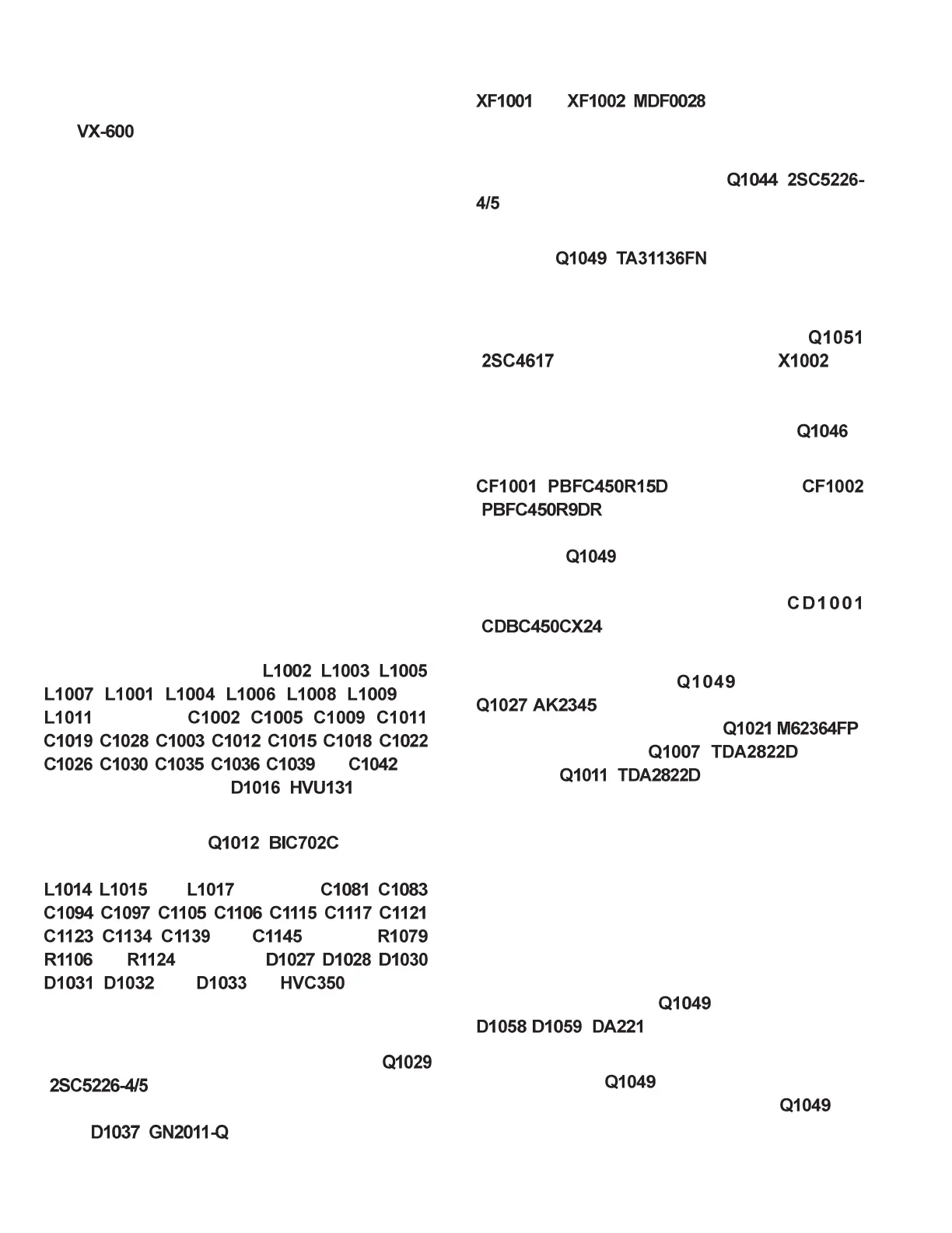
Receive Signal Path
Front-end RF Amplifier
Incoming RF from the antenna jack is delivered to the
RF Unit and passes through a low-pass filter and high-
pass filter consisting of coils
, , ,
, , , , , and
, capacitors , , , ,
, , , , , , ,
, , , , and , and
antenna switching diode
( ).
Signals within the frequency range of the transceiver
are then amplified by ( ) and enter a
varactor-tuned band-pass filter consisting of coils
, , and , capacitors , ,
, , , , , , ,
, , , and , resisters ,
and , and diodes , , ,
, , and (all ) before de-
livery of the RF signal to the first mixer.
First Mixer
Buffered output from the VCO is amplified by
( ) to provide a pure first local signal be-
tween 355.75 and 467 MHz for injection to the first
mixer
( ). The 44.25 MHz first mixer
product then passes through monolithic crystal filters
and ( , ±5.5 kHz BW) to strip
away all undesired mixer products.
IF Amplifier
The first IF signal is amplified by (
).
The amplified first IF signal is applied to FM IF sub-
system IC ( ), which contains the
second mixer, second local oscillator, limiter ampli-
fier, noise amplifier, and S-meter amplifier.
A second local signal is generated by
( ) using the 14.6 MHz crystal as a
reference, producing a 43.8 MHz signal; this which
yields a 450 kHz second IF when the reference sig-
nal is mixed with the first IF signal within
.
The second IF then passes through the ceramic filter
( : wide channels),
( : narrow channels) to strip away all
but the desired signal, and is applied to the limiter
amplifier in
, which removes amplitude varia-
tions in the 450kHz IF, before detection of the speech
by the ceramic discriminator
( ).
Audio Amplifier
Detected audio from is applied to
( ) and the audio low-pass filter, and
then through the volume control (
: )
to the audio amplifier
( ;external
speaker) or
( ;internal speaker), pro-
viding up to 0.5 Watt to the optional headphone jack
or 16-ohm loudspeaker.
Attention: Audio output is BTL output. Both sides
of the audio output are above ground, and this line
must not be connected to a speaker line which uses a
grounded shield.
Squelch Control
The squelch circuitry consists of a noise amplifier and
band-pass filter within
, and noise detector
/ ( ).
When no carrier received, noise at the output of the
detector stage in is amplified and band-pass
filtered by the noise amplifier section of
and
the network between pins 7 and 8, and then rectified
by D1058.