18
Alignment
Whenever possible, alignments should be made with
oscillator shields and circuit boards firmly affixed in
place. Also, the test equipment must be thoroughly
warmed up before beginning.
Note: Signal levels in dB referred to in the alignment pro-
cedure are based on 0 dBμ EMF = 0.5 μV (closed circuit).
When connecting the
plug into the
jack of the , you must remove the
plastic cap and its mounting screws prior to
programming. Please remember to re-attach
the cap and screws when the programming is
complete.
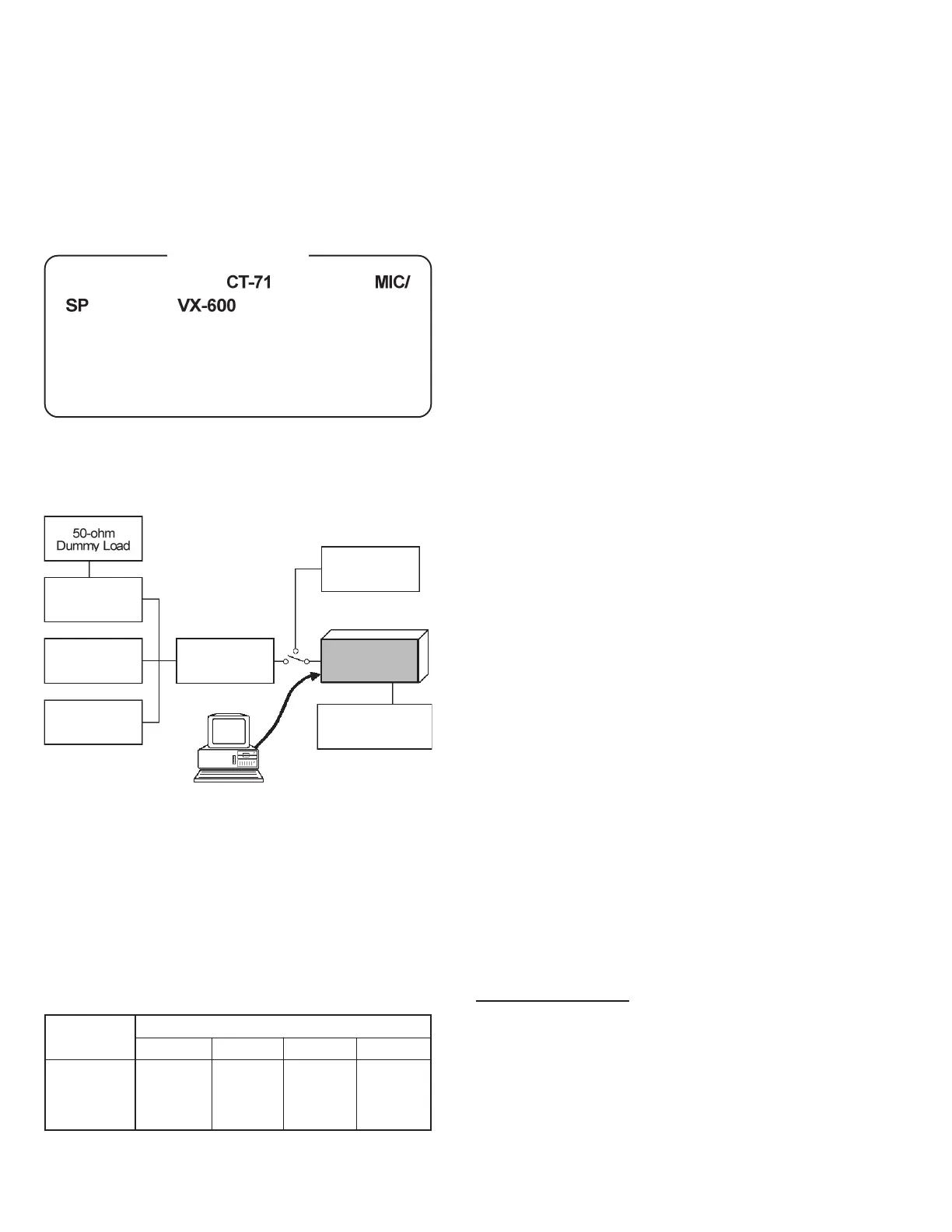
Set up the test equipment as shown for transceiver
alignment, and apply 7.5V DC power to the trans-
ceiver.
The alignment tool outline
Installation of the Alignment Tool
The “alignment mode” is a software-based protocol,
accessed by an “Alignment Mode” command from
the computer while switching the transceiver on. It
is operated by the alignment tool automatically. Dur-
ing use of the alignment mode, normal operation is
suspended. The alignment tool program provides all
needed operation capability.
The alignment tool consists of an executable file
“SVC39.exe” and an accompanying configuration file
“SVC39.cfg” which should be loaded per standard
DOS procedures. Create a suitable directory, then
copy these files from the distribution diskette into
the new directory. For example, if copying the file
from Drive A, use the following DOS command se-
quence:
c:\ mkdir align900 [enter]
c:\ cd align900 [enter]
c:\align900\ copy a:SVC39.*
No further installation steps are required. If you wish
to utilize a different name for the alignment direc-
tory, it will not matter to the executable file.
Booting the Alignment Tool
Change to the “align900” directory (or the directory
name you utilized in the previous section). Now type
on the command line: SVC39 [ENTER] to boot the
alignment tool.
Entering the Alignment Mode
To enter the alignment mode, turn the transceiver
off, then press [0] on the computer keyboard. Now,
turn the transceiver back
On. When the command
has been successful, a message on the computer
screen will confirm that the transceiver is now in the
“Alignment” mode.
Action of the Switches
When the transceiver is in alignment mode, the [PTT],
[MON], and [DIAL] switches, as well as the Dial, are
disabled. In the Alignment mode, all of the
transceiver’s operation is remotely controlled by the
PC.
Important Note
The transceiver must be programmed for use in the
intended system before alignment is attempted. The
RF parameters are loaded from the file during the
alignment process.
In order to facilitate alignment over the complete
operating range of the equipment, it is recommended
that the channel data in the transceiver be preset as
per the chart below.
Inline Wattmeter
Deviation Meter
Frequency
Counter
RF Sampling
Coupler
RF Signal
Generator
Transceiver
Power Supply
7.5V DC
CT-71 connection
Cable
PC
MIC/SP
COM port
Channels
Frequency (Simplex)
Type- AS1
Band-LOW
Band-MID
Band-HIGH
400.000
415.000
430.000
440.000
455.000
470.000
Type- CS Type- D
450.000
470.000
485.000
Type- F
485.000
498.500
512.000
 Loading...