Discrete Controller Interface for non-TAC Systems LD-16 Door Operator - Modernization
74 © Vertical Express
Discrete Controller Interface for non-TAC
Systems
Discrete Controller Interface Setup
See also:
• I/O Signal Definitions on page 75.
• I/O Wiring Diagram on page 76.
If a CAN board is present, remove it to use the discrete interface ports.
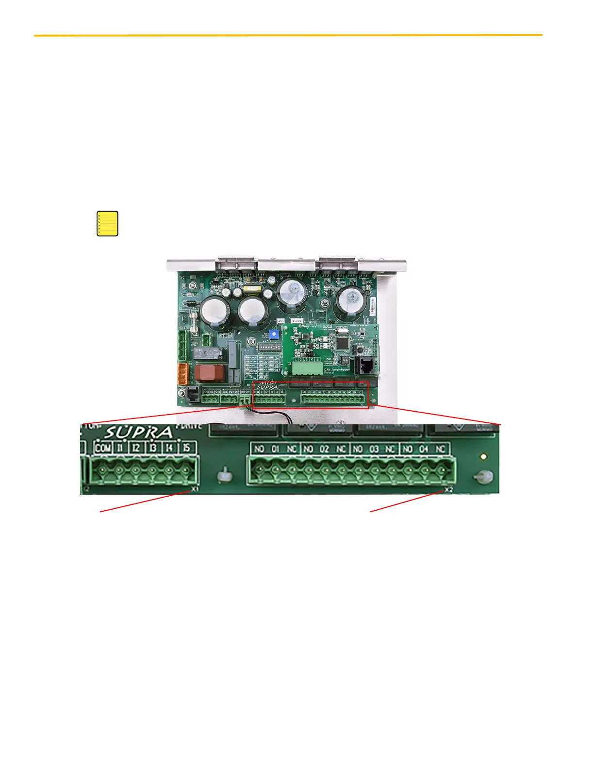
Figure 60 - Discrete Controller Interface
X1
• INPUTS enter the board here.
• Do not wire any controller power supply to any pin.
• Circuits designed for low current.
• Suggested relays = <100mA.
COM = Common
I1 = OPEN
I2 = CLOSE
I3 = NUDGING
I4 = INSPECTION
I5 = ALT SPEED
NO = Normally Open
O1 = Door Open Limit
NC = Normally Closed
O2 = Door Close Limit
O3 = Reopening
O4 = SIX
X2
• OUTPUTS exit the board here.
• Relay output contacts are rated at
5A, 30VDC or 5A, 250VAC.