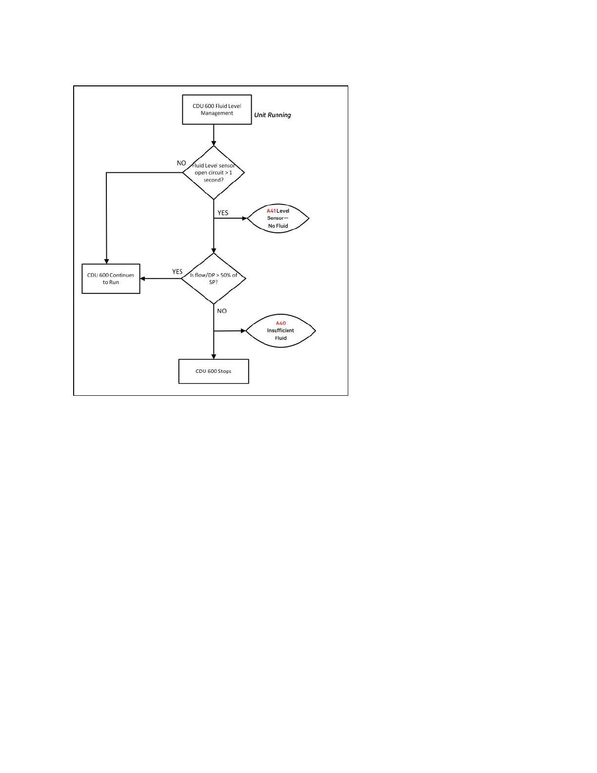
Figure 4.17 Fluid Level Management Flow Chart When Running
Secondary Supply Temperature Control Logic
The secondary fluid temperature is monitored close to the secondary circuit supply connection Three temperature sensors
are positioned here to give extended component redundancy (T2a, T2b, and T2c). The controller takes an average between
all 3 readings as its input value.
• If the difference between sensors exceeds a default of 1.0°C (2°F), an A47, A48, or A49—Secondary Temp T2a
(T2b or T2c) Diff Fault alarm is raised after a default delay of 30 seconds. The controller only reads and averages
the two remaining healthy sensors.
• If any of the T2 temperature sensors go open circuit, then an A02 (A03 or A04)—T2a (T2b or T2c) Secondary
Temperature Sensor Fault alarm is raised with no time delay. The controller only reads and averages the two
remaining healthy sensors.
Temperature sensor (T4) monitors the secondary circuit return temperature and is used in conjunction with the flow rate to
calculate the heat transfer duty.
4 Operation Proprietary and Confidential ©2025 Vertiv Group Corp. 47
Vertiv™ CoolChip CDU 600 Operation and Maintenance Guide



 To Next Page