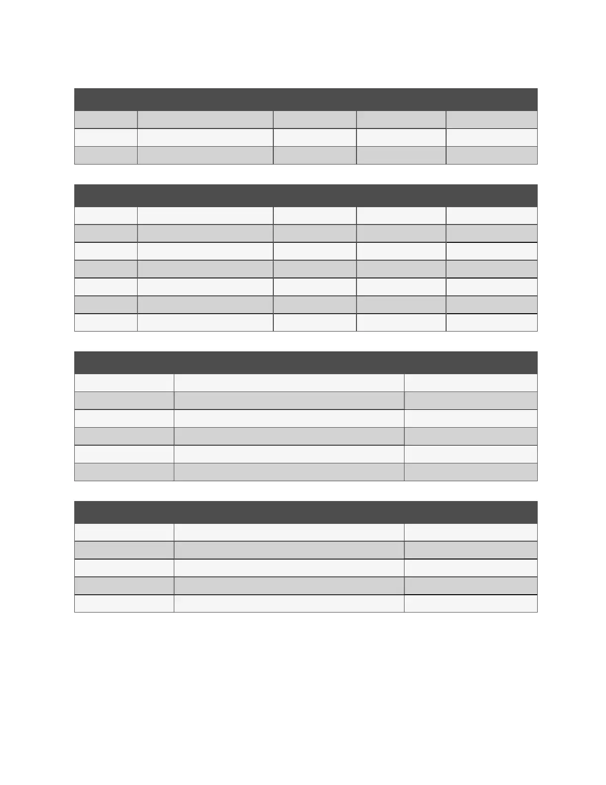
ID Description ADC Value Electrical Processed
UI14 Ambient Sensor – Temperature T3 0 0.00 ohms 0.00 °C
UI15 Primary Return Temp. T5 0 0.00 ohms 0.00 °C
UI16 Control Valve Feedback 0 0.00 V 0.00%
Table 4.37 I/O Diagnostics—Universal Inputs 9 to 16 (continued)
ID Description ADC Value Electrical Processed
RI01 Underfloor Leak Tape 0 0 ohms 0
RI02 Secondary Flow Temperature T2a 0 0 ohms 0.00 °C
RI03 Secondary Flow Temperature T2b 0 0 ohms 0.00 °C
RI04 Secondary Flow Temperature T2c 0 0 ohms 0.00 °C
U17 Secondary Fluid Qualityi -- Turbidity 0 0.00 mA 0.0 NTU
U18 Secondary Fluid Quality -- PH 0 0.00 mA 0.00 PH
U19 Secondary Fluid Quality -- Conductivity 0 0.00 mA 0.0 S/cm
Table 4.38 I/O Diagnostics—Resistive Inputs 1 to 4 and Universal Inputs 17 to 19
ID Description State
DI01 Flood Tray Level Switch Open
DI02 Fluid Level Sensor #1 Open
DI03 Fluid Level Sensor #2 Open
DI04 Reservoir Tank Level Sensor - High Open
DI05 Reservoir Tank Level Sensor - Low Open
DI06 Reservoir Tank Level Sensor – Very Low Open
Table 4.39 I/O Diagnostics—Digital Inputs 1 to 6
ID Description State
DO01 Unit Fill Pump P3 OFF
DO03 PS3/PS4 Select OFF
DO05 Reservoir Tank Fill Pump P4 OFF
DO06 Extended Alarm OFF
AO01 Cooling Valve %
Table 4.40 I/O Diagnostics—Digital and Analogue Outputs
4.2.11 Group Control Status Screen
The Group Control Status screen provides that status information of other CDUs connected to the CANbus network. Access
the Group Control Status Screen from page 6 of the Control System Status screen.
4 Operation Proprietary and Confidential ©2025 Vertiv Group Corp. 39
Vertiv™ CoolChip CDU 600 Operation and Maintenance Guide