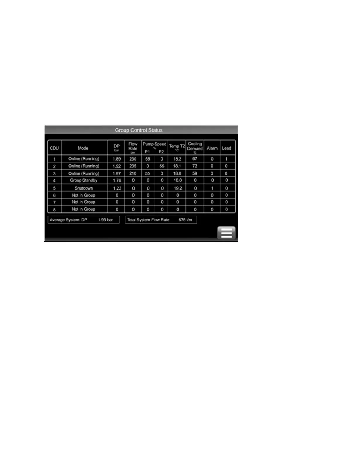
Units become self organizing when in group control. The lead unit is automatically selected which coordinates the running
state of each unit in group based on:
• Configured level of redundancy
• System pressure requirements
• Alarm conditions
Changes to the group settings or system settings can be made via any CDU 600 touchscreen user interface at any time and
are automatically synced across the network.
Figure 6.3 Group Control Status Screen
5.3.2 Group Control—Network Termination Resistors
The CDU 600 controller includes an onboard 120 ohm resistor which can be activated by fitting a hardware jumper. If only one
CDU 600 unit is installed, the resistor does not require activation. For a two unit installation, both units should have the
termination resistors enabled. For three or more units, units 1 and n should have the termination resistors enabled, while units
between should be disabled. Failure to disable the middle resistors could result in intermittent communications. See Figure 6.4
on the facing page and Figure 6.5 on the facing page for the location of the jumper to enable/disable the termination
resistor (the jumper is fitted by default and must be removed if not required).
62 Proprietary and Confidential ©2025 Vertiv Group Corp.
Vertiv™ CoolChip CDU 600 Operation and Maintenance Guide