2.3.6 Charger Module
In AC mains mode, the charger module, shown in Figure 2.10 below, charges the system battery modules
or external battery cabinet. Each charger module is rated to deliver 10-A charging current. The charger
module has an independent control function and maintains real-time communication with the system and
the battery modules to ensure stable charging and fault protection.
The charger module may be added or replaced on-line with no interruption or danger to the user,
connected battery system or connected equipment.
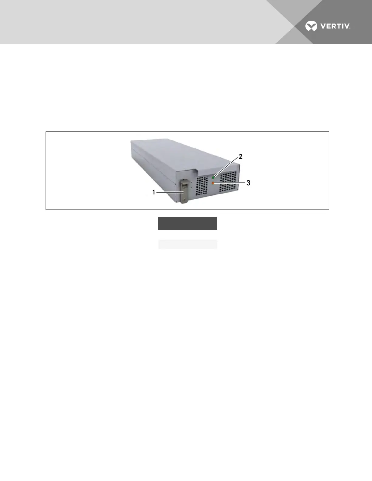
Figure 2.10 Charger module
ITEM DESCRIPTION
1 Locking Lever
2 Status LED (green)
3 Fault LED (yellow)
2.3.7 External Battery Cabinet (EBC)
The external battery cabinet, shown in Figure 2.11 on the facing page, is divided into 9rows: the upper
7rows are used for the intelligent battery modules, and the lower 2 rows are used for overcurrent
protection for each battery cabinet. For normal operation, 2battery modules must be inserted in the same
row of the frame to create a complete string. The battery module strings work in parallel to provide longer
back-up time for the UPS. The Liebert APS can be configured with up to 4external battery cabinets.
Vertiv | Liebert® APS™ Installer/User Guide | 20