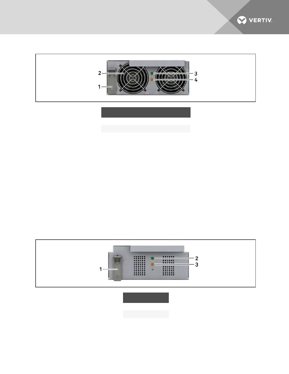
Figure 2.8 Power module
ITEM DESCRIPTION ITEM DESCRIPTION
1 Locking Lever 3 Status LED (green)
2 Fan 4 Fault LED(yellow)
2.3.5 Battery Module
When AC utility fails, the battery module supplies power to the load. Each battery module contains
6individual 12-V, valve-regulated lead-acid (VRLA) battery blocks. Two battery modules are connected in
series to form a battery string.
Each battery module, shown in Figure 2.9 on the next page,has monitoring and controls that isolate the
battery module in the event of a battery failure. The battery strings are connected in parallel to provide
back-up time and/or redundancy.
NOTE: Two battery modules must be installed in the same row to make a complete battery string.
The battery modules may be added or replaced on-line with no interruption or danger to the connected
equipment if the UPS is not operating on battery.
Under normal operation, the green status LED blinks continuously and the yellow fault LED is Off. For any
other condition, refer to Troubleshooting on page 69.
Figure 2.9 Battery module
ITEM DESCRIPTION
1 Locking Lever
2 Status LED (green)
3 Fault LED (yellow)
Vertiv | Liebert® APS™ Installer/User Guide | 19