2. Push the module in slowly until about 1cm (1/2in) of the module remains outside the bay, as
shown in Figure 3.12 below, then press it firmly and smoothly to ensure that it is fully inserted.
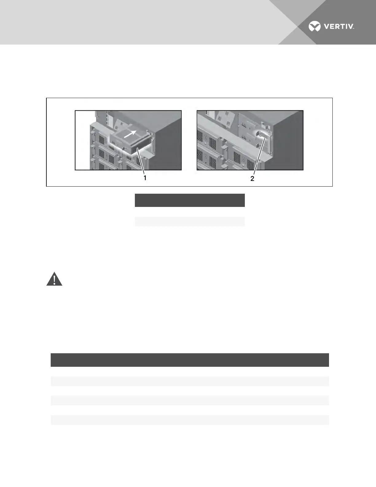
3. Pull out the lock lever slightly, then press the lever to the right into the bracket.
Figure 3.12 Insert the module and engage the lock lever
ITEM DESCRIPTION
1 Push in smoothly and firmly until fully inserted.
2 Pull out slightly and slide lock lever to the right.
4. Use a #2 Phillips screwdriver to install the screws into the holes on each end of the inserted
module.
5. Replace the user-interface module and display bezel.
3.7 Cable Connections
WARNING! Risk of electric shock. Can cause injury or death. Disconnect local and remote
power supplies before working within. Read this section thoroughly before attempting to install
wiring to this unit. Ensure that all the UPS input sources are disconnected off before
attempting to install wiring to this unit. This UPS cables should be connected by a properly
trained and qualified electrician.
Refer to the unit model number in Table 3.1 below to determine the instructions to use for installation.
UPS MODEL # DIGITS1-3 FRAME TYPE MANUAL SECTION
AS1 or ASA 10 Bay Transformer-free Connecting Cables on a Transformer-free UPS on page 32
AS2 or ASB 16 Bay Transformer-free Connecting Cables on a Transformer-free UPS on page 32
AS3 or ASC 12 Bay Transformer-based Connecting Cables on a Transformer-Based UPS on page 36
AS4 or ASD 16 Bay Transformer-based Connecting Cables on a Transformer-Based UPS on page 36
AS5 or ASE 10 Bay Transformer-free Connecting Cables on a Transformer-free UPS with Dual Inverter Frames on page 41
AS6 or ASF 16 Bay Transformer-free Connecting Cables on a Transformer-free UPS with Dual Inverter Frames on page 41
Table 3.1 Cable connection method reference
3.7.1 Connecting Cables on a Transformer-free UPS
A junction box is factory-installed on each model of the Liebert APS to ease cable connection.
Vertiv | Liebert® APS™ Installer/User Guide | 32