5 OPERATION AND DISPLAY PANEL
The user-interface module is the operation and display panel composed of an LED mimic power flow
diagram, fault LED indicator and LCD screen to show detailed operational information and UPS alarm list
using the menu buttons.
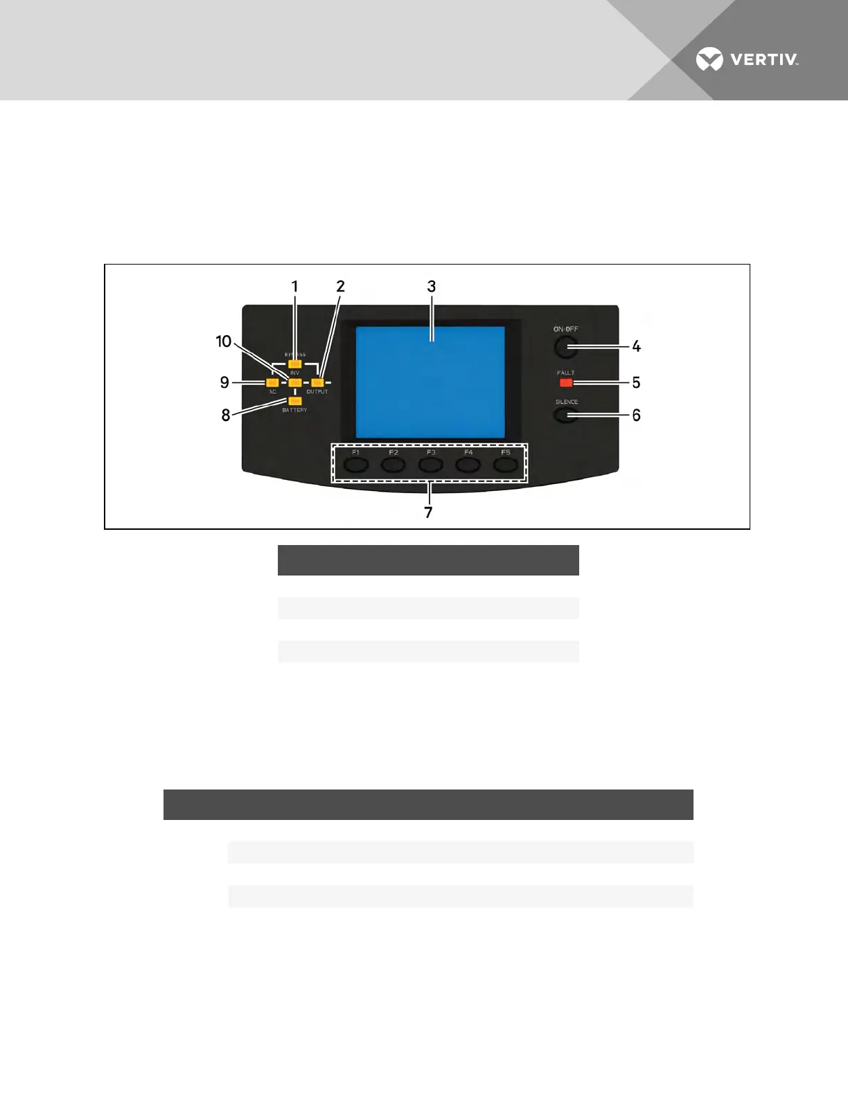
Figure 5.1 Operation and display on the user-interface module
ITEM DESCRIPTION ITEM DESCRIPTION
1 Bypass LED 6 Alarm silence button
2 Output LED 7 Menu buttons
3 LCD screen 8 Battery LED
4 On/Off button 9 AC LED
5 Fault LED 10 Inverter LED
5.1 Mimic LEDs
The mimic power-flow LEDs indicate current operating state of the UPS. Table 5.1 below. describes the
LEDstates.
LED STATE DESCRIPTION
AC LED
On (Green) The rectifier is functioning normally
Flashing (Green) The AC mains is normal, but the rectifier is not functioning properly
On (Red) The rectifier is faulty
Off The AC mains is abnormal, and the rectifier is not functioning
Table 5.1 LED descriptions
Vertiv | Liebert® APS™ Installer/User Guide | 57