Figure 4.3 REPO connector pin layout
POSITION NAME DESCRIPTION
9 REPO +12V REPO power, 12VDC 100mA
10 REPO Coil -NO REPO normally-open nodes, shorting pins 9 and 10, REPO is triggered
11 REPO Coil -NC REPO normally-closed nodes (fail-safe), shorting pins 9, 10, 11, 12, and opening pins 11 and 12, REPO is triggered
12 GND GND
Table 4.2 Pin definition of the REPO dry contact
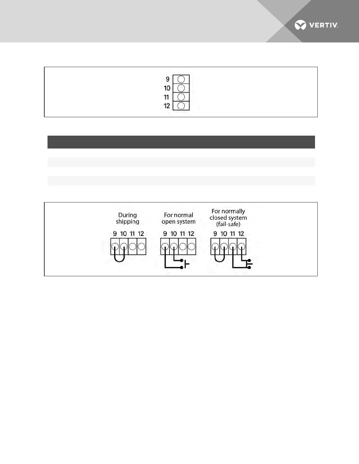
Figure 4.4 REPO switch connections
NOTE: A jumper is factory-installed between Pins 9 and 10 to disable the Main Control Switch, which
prevents the UPS from being started accidentally during shipment and installation. This jumper must
be removed before the unit can be started. If the installation does not require connection to a REPO
system, the factory-installed jumper must be removed.
4.4 Long-run-time (LRT) Battery-temperature-probe Terminals
The Liebert APS contains a temperature-compensated battery-charging system. To use this feature with
external LRT battery systems, connect Pins 13-16 of the contact terminal strip to a temperature sensor.
Vertiv | Liebert® APS™ Installer/User Guide | 54