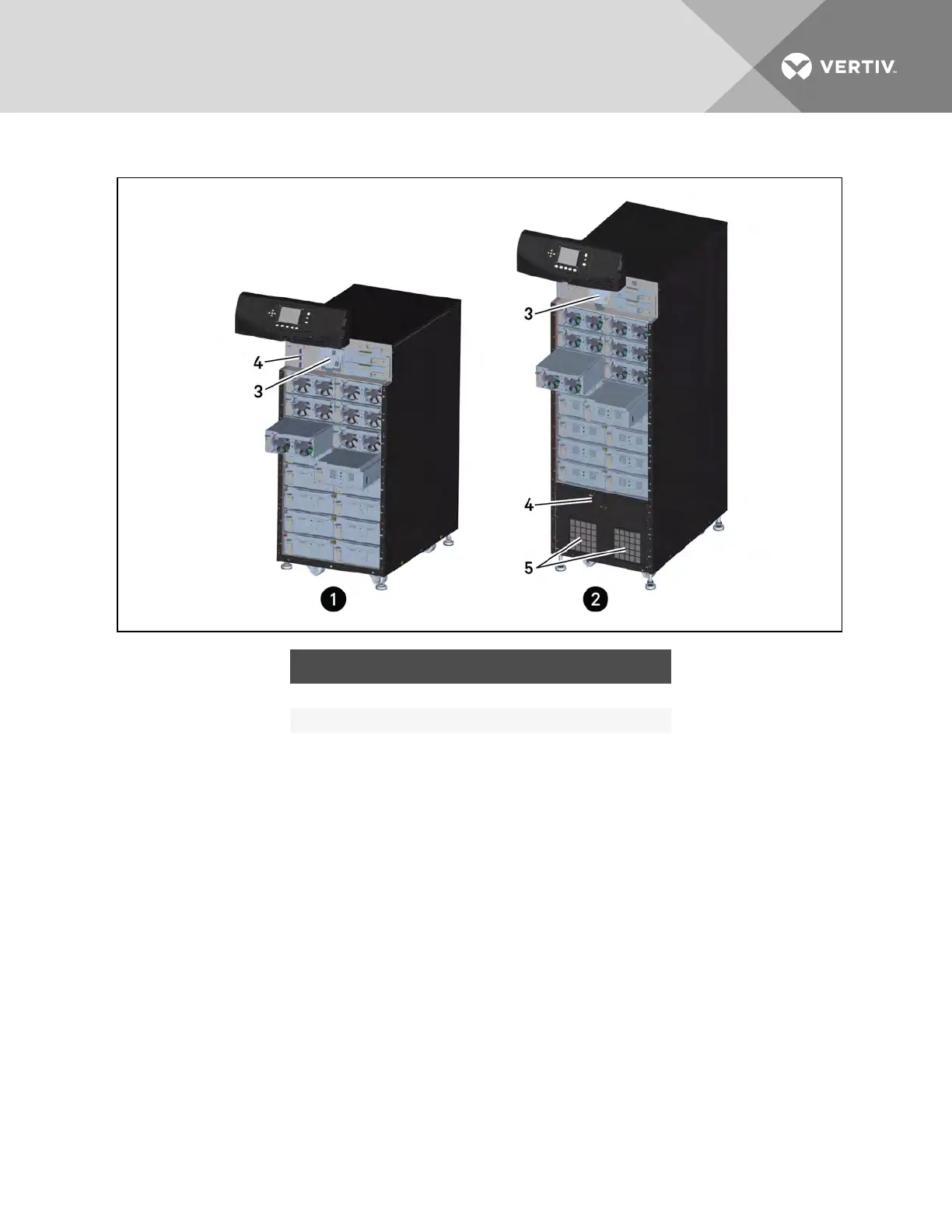
Figure 2.5 Example UPS frames with bezels removed
ITEM DESCRIPTION ITEM DESCRIPTION
1 16-bay, transformer-free UPS 4 Manual bypass breaker
2 16-bay, transformer-based UPS 5 Fans
3 Fan, behind display bracket
2.3.2 User-Interface Module
The user-interface module, shown in Figure 2.6 on the next page,is the primary source of communication
between the UPS and the user. The user interface module lets you:
• View the UPS status
• Configure the system
• Review the event log
• Silence the audible alarm
Refer to Operation and Display Panel on page 57 for details on operating the user interface module.
Vertiv | Liebert® APS™ Installer/User Guide | 17