Figure 2.6 User-interface module
2.3.3 System-Control Module and System-Monitor Module
The system-control module and the system-monitor module are the communication backbone of the UPS.
They gather input from all modules and process the data to control system operation and monitor the
condition of each module. Except for the silkscreen, the appearance of the system-control module and the
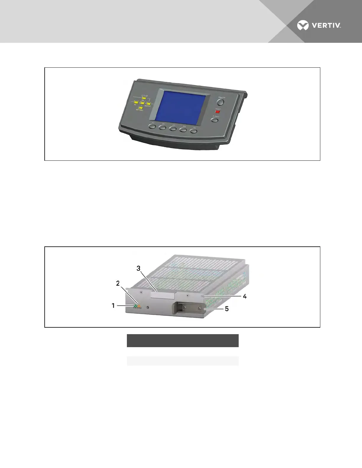
system-monitor module appear as shown in Figure 2.7 below.
Under normal operation, the green status LED blinks and the yellow fault LED is Off. For any other
condition, refer to Troubleshooting on page 69.
Figure 2.7 Example of system-control and system-monitor module
ITEM DESCRIPTION ITEM DESCRIPTION
1 Status LED (green) 4 Securing hole
2 Fault LED (yellow) 5 Locking lever
3 Handle
2.3.4 Power Module
Each power module, shown in Figure 2.8 below, is an independent 5-kVA unit, consisting of a power-
factor-corrected rectifier, battery charger, and inverter with associated monitoring and control circuitry.
The modules are connected in parallel for greater capacity and/or redundancy.
The power modules may be added or replaced on-line with no interruption or danger to the connected
equipment or user.
Vertiv | Liebert® APS™ Installer/User Guide | 18