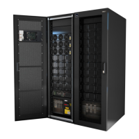
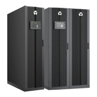
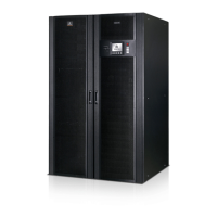
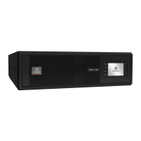
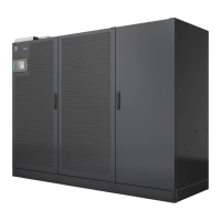
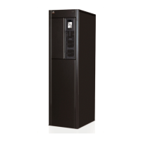
2.2 Features
• Flexible extension of capacity, up to 15 or 20kVA modular power, depending upon frame rating
• N + 1 redundancy, improving availability
• Modular design, modules hot-swappable by user
• Intelligent battery management
• External large batteries can be connected
• Internal automatic and manual bypass
• Transformer-based UPS frames provide output isolation transformer
• Optional 10-A battery charger module
• Continuous system monitoring
• User-friendly interface with audible alarms and event logs
• Supporting hot-pluggable and online update
• Compatible with backup generators
Standard Components
• UPS frame
• User-interface module for comprehensive user indications and programmable controls
• System-control modules and system-monitor module for system monitoring and
communications
• Power modules for power conditioning
• Battery modules for back-up power
• Charger module option for charging batteries and long run-time applications
• External battery cabinet prolongs system run time
Communications
• Dry contacts
• Liebert IntelliSlot communication ports
• USB port
2.3 Major Components
This section provides a general description of each component and its functions. Please review this
section carefully, as it will give you a better understanding of how the UPS operates.
2.3.1 UPS Frame
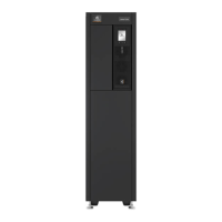
All UPS components are located in the Liebert APS frame. The front of the UPS consists of a series of
plastic bezels. Grasp the bezels from the sides and pull straight out to remove the bezel and reveal the
battery/power-module bays. The standard-model frame provides cooling fans and a manual-bypass
breaker on the top. The transformer-model frame provides a manual-bypass breaker on its bottom and
fans on both top and bottom. The user-interface module is located above the power/battery-module bays
for easy access, operation and for viewing UPS operating information. On the lower-right of the user-
interface module are the system-control module bays.The UPS frames are shown in Figure 2.5 below.
NOTE: In the figure, the power module and battery module are extended for illustration purposes only.
Extending more than one module at a time could cause the unit to tip over.
Vertiv | Liebert® APS™ Installer/User Guide | 16
 Loading...
