USER MANUAL-S600E
74
S600E
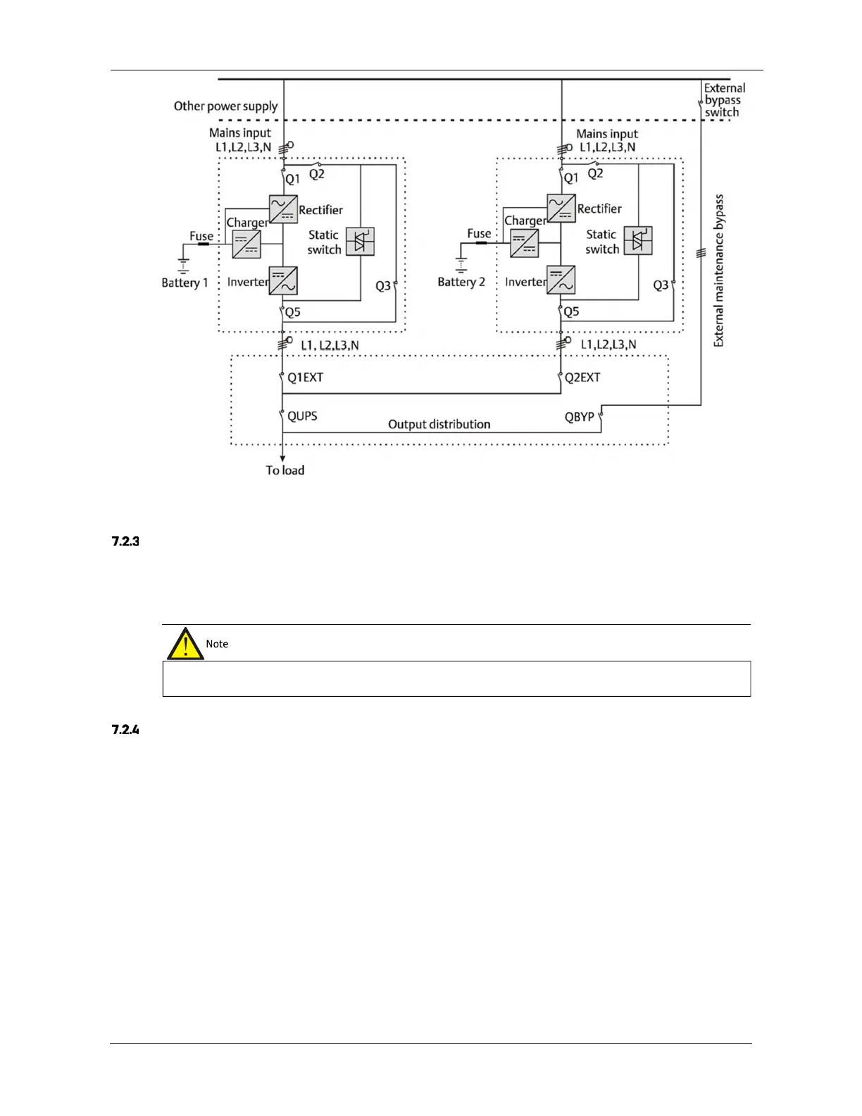
Figure 7-1 Circuit diagram of typical parallel system (with common input, separate batteries and output)
Power Cables
The power cable wiring is similar to that of the UPS module. Refer to 3.1 .
The bypass and rectifier input supplies must be use the same neutral line input terminal. If the input is fitted with a current
leakage protection device, the device must be fitted upstream of the neutral line input terminal.
Parallel cables
Shielded and double-insulated parallel cables must be interconnected in a ring configuration between the UPS
modules, as shown in Figure 7-2. Method: connect a parallel cable between the PARA1 port on one module and the
PARA2 port on the next module. Repeat this step for all the other parallel cables.
The ring connection ensures the reliability of the control of the parallel system. Be sure to verify that the cables are
connected securely before starting up the system!
The power cables (including the bypass input cables and UPS output cables) of each UPS module should be of the same
length and specifications to facilitate load sharing.