USER MANUAL-S600E
87
S600E
Table 8-4 Setting the UPS switch-on and switch-off signal input function
off signal input function enabled
off signal input function disabled
2.
Insert the relay card into the UPS.
a)
Remove the Intellislot port cover (see Figure 3-6) on the front panel. Do not throw the screws away.
b)
Align the relay card with the Intellislot port, insert the relay card into the port along the grooves on both sides of
the port.
c)
Secure the relay card in place through the fixing holes on the relay card panel using the screws from step a).
3.
Connect the cable.
You can select an optional cable according to your needs, or prepare your own, in accordance with Table 8-4 and
Figure 8-10 - Figure 8-12. Connect the cable end with the DB25 male connector to the DB25 connector of the relay
card, and the other end to the user equipment.
Troubleshooting
See Table 8-5 for relay card troubleshooting information.
Table 8-5 Troubleshooting
1
The dry contact output signal
the UPS status changes
Check that the relay card has been inserted into the
Intellislot port correctly
2
The UPS does not respond to the UPS switch
contact input signal
set to the 'ON' position
The relay card installation method is the same as for the SIC card, as described in 8.2.3 . Refer to 3.2.8 for
information about wiring and routing the signal cables.
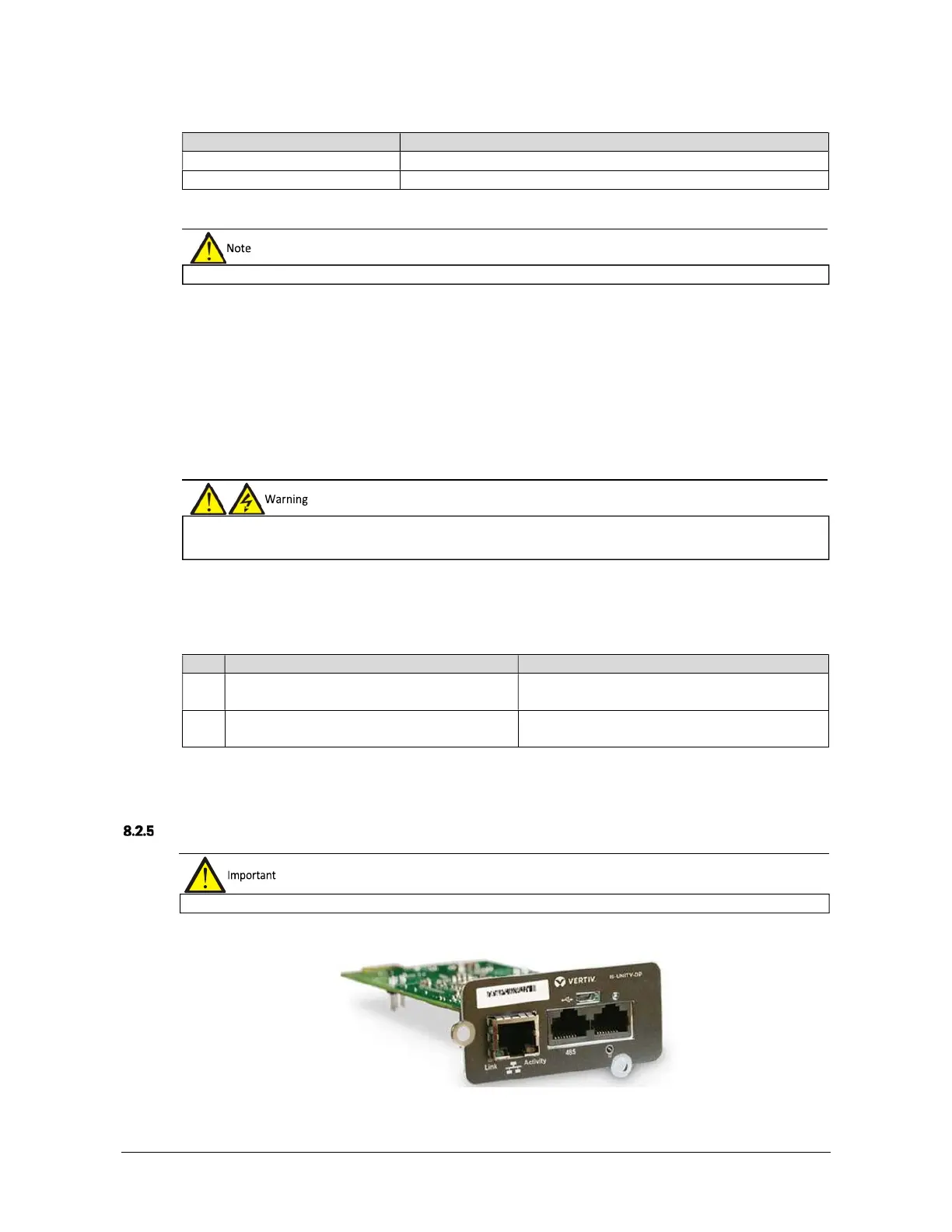
IS-UNITY-DP Card
The appearance of IS-UNITY-DP card is shown in Figure 8-14.
Figure 8-14 IS-UNITY-DP card
pluggable, therefore it may be
installed without shutting the UPS down.
The DB25 connector must be connected to a SELV circuit. Failure to observe this could damage the relay card and even
lead to accidents.
g shielded cables in order to increase EMC.
 Loading...


